background image

AK45 Service Manual 


01/12/2003


- - 

- 64 

- NC 

  LV 

Not 

connected 

- - 

- 63 

- NC 

  LV 

Not 

connected 

27 56 

45 62 48 AVSS 


Analog 

ground 

- - 

- 61 

- AVSS    X 

Analog 

ground 

28 55 

44 60 47 MONO_IN IN  LV 

Mono 

input 

- - 

- 59 

- NC 

  LV 

Not 

connected 

29 54 

43 58 46 VREFTOP  

Reference voltage IF A/D 
converter 

30 

53 

42 

57 

45 

SC1_IN_R 

IN 

LV 

SCART 1 input, right 

31 

52 

41 

56 

44 

SC1_IN_L 

IN 

LV 

SCART 1 input, left 

32 

51 

55 

43 

ASG1 


AHVSS 

Analog Shield Ground 1 

33 

50 

40 

54 

42 

SC2_IN_R 

IN 

LV 

SCART 2 input, right 

34 

49 

39 

53 

41 

SC2_IN_L 

IN 

LV 

SCART 2 input, left 

35 

48 

52 

40 

ASG2 


AHVSS 

Analog Shield Ground 2 

36 

47 

38 

51 

39 

SC3_IN_R 

IN 

LV 

SCART 3 input, right 

37 

46 

37 

50 

38 

SC3_IN_L 

IN 

LV 

SCART 3 input, left 

38 

45 

49 

37 

ASG4 


AHVSS 

Analog Shield Ground 4 

39 

44 

48 

36 

SC4_IN_R 

IN 

LV 

SCART 4 input, right 

40 

43 

47 

35 

SC4_IN_L 

IN 

LV 

SCART 4 input, left 

41 

- 46 

- NC 

  LV 

or 

AHVSS 

Not 

connected 

42 42 

36 45 34 AGNDC   

Analog 

reference 

voltage 

43 41 

35 44 33 AHVSS   

Analog 

ground 

- - 

- 43 

- AHVSS    X 

Analog 

ground 

- - 

- 42 

- NC 

  LV 

Not 

connected 

- - 

- 41 

- NC 

  LV 

Not 

connected 

44 40 

34 40 32 CAPL_M   

Volume 

capacitor 

MAIN 

45 

39 

33 

39 

31 

AHVSUP 


Analog power supply 8V 

46 38 

32 38 

30 CAPL_A   

Volume 

capacitor 

AUX 

47 

37 

31 

37 

29 

SC1_OUT_L 

OUT 

LV 

SCART output 1, left 

48 

36 

30 

36 

28 

SC1_OUT_R 

OUT 

LV 

SCART output 1, right 

49 35 

29 35 27 VREF1 


Reference 

ground 

50 

34 

28 

34 

26 

SC2_OUT_L 

OUT 

LV 

SCART output 2, left 

51 

33 

27 

33 

25 

SC2_OUT_R 

OUT 

LV 

SCART output 2, right 

52 

- 32 

- NC 

  LV 

Not 

connected 

53 32 - 

31 24  NC 


LV 

Not 

connected 

54 31 

26 30 23 DACM_SUB 

OUT 

LV 

Subwoofer 

output 

55 30 - 

29 22  NC 


LV 

Not 

connected 

56 29 

25 28 21 DACM_L  OUT 

LV 

Loudspeaker 

out, 

left 

57 28 

24 27 20 DACM_R  OUT 

LV 

Loudspeaker 

out, 

right 

58 27 

23 26 19 VREF2 


Reference 

ground 

59 26 

22 25 18 DACA_L  OUT 

LV 

Headphone 

out, 

left 

60 25 

21 24 17 DACA_R  OUT 

LV 

Headphone 

out, 

right 

- - 

- 23 

- NC 

  LV 

Not 

connected 

- - 

- 22 

- NC 

  LV 

Not 

connected 

61 24 

20 21 16 RESETQ  IN  X 

Power-on-reset 

62 23 - 

20 15  NC 


LV 

Not 

connected 

63 22 - 

19 14  NC 


LV 

Not 

connected 

64 21 

19 18 13 NC 


LV 

Not 

connected 

65 20 

18 17 12 I2S_DA_IN2 

IN  LV 

I

2

S2-data input 

66 19 

17 16 11 DVSS 


Digital 

ground 

- - 

- 15 

- DVSS    X 

Digital 

ground 

- - 

- 14 

- DVSS    X 

Digital 

ground 

67 18 

16 13 10 DVSUP   

Digital 

power 

supply 

5V 

- - 

- 12 

- DVSUP    X 

Digital 

power 

supply 

5V 

- - 

- 11 

- DVSUP    X 

Digital 

power 

supply 

5V 

68 17 15  10 9  ADR_CL  OUT LV 

ADR 

clock 


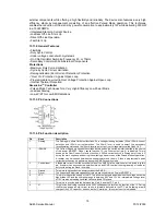
13.4.VDP313xY 

13.4.1.Introduction 

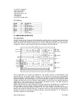
The VDP 313xY is a video IC family of high-quality single-chip video processors. Modular design and a 
sub-micron technology allow the economic integration of features in all classes of TV sets. The VDP 
313xY family is based on the VDP 31xxB including YC

R

C

inputs for DVD component signals. 

The VDP 313xY includes complete video, display and deflection processing. All processing is done 
digitally, the video frontend and video backend are interfacing to the analog world. Most functions of the 
VDP can be controlled by software via I

2

C-Bus interface  

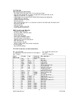
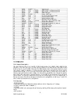
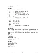
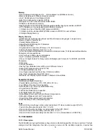
Summary of Contents for EU2845ST

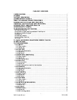
Page 1: ...SERVICE MANUAL EU2845ST 16 9 CTV NOV03 SERVEU2845 ...

Page 2: ... TDA1308 4 12 SAW FILTERS 4 13 IC DESCRIPTIONS 5 13 1 LM317T 5 13 1 1 Description 5 13 1 2 Features 5 13 2 TDA1308T 5 13 2 1 General Description 5 13 2 2 Features 5 13 2 3 Pinning 6 13 3 MSP34X0G MSP3410G 6 13 3 1 Description 6 13 3 2 Features 7 13 3 3 Pin connections 7 13 4 VDP313xY 8 13 4 1 Introduction 8 13 4 2 Features 9 13 4 3 Pin Connections and short descriptions 9 13 5 TEA6415C 10 13 5 1 G...

Page 3: ...L Tuner Control 2 Low Byte 33 Option 13 PLL Tuner Control 2 Mid Byte 34 Option 14 PLL Tuner Control 2 High Byte 34 Option 15 PLL Tuner VHF LOW VHF HIGH Crossover Low Byte 34 Option 16 PLL Tuner VHF LOW VHF HIGH Crossover High Byte 34 Option 17 PLL Tuner VHF HIGH UHF Crossover Low Byte 34 Option 18 PLL Tuner VHF HIGH UHF Crossover High Byte 34 Option 19 PIP PLL Tuner Control 1 Byte 35 Option 20 PIP...

Page 4: ...ption 47 Volume Offset Center 40 Option 48 Volume Offset Rear 40 Option 49 Surround Delay 40 Option 50 FM Prescale 40 Option 51 NICAM Prescale 40 Option 52 Scart Input Prescale 40 Option 53 I2S Prescale 40 Option 54 Scart Output Prescale 40 Option 55 Speaker Setup 41 Option 56 Audio Options Available Or Not 41 Option 57 Stereo Threshold 41 Option 58 MSP Audio Flags 42 Option 59 NICAM Threshold 42 ...

Page 5: ...s of UV1316 1 Member of the UV1300 family small sized UHF VHF tuners 2 Systems CCIR B G H L L I and I OIRT D K 3 Digitally controlled PLL tuning via I2 C bus 4 Off air channels S cable channels and Hyperband 5 World standardized mechanical dimensions and world standard pinning 6 Compact size 7 Complies to CENELEC EN55020 and EN55013 Pinning 1 Gain control voltage AGC 4 0V Max 4 5V 2 Tuning voltage...

Page 6: ...ers the sound processing of all analog TV Standards worldwide as well as the NICAM digital sound standards The full TV sound processing starting with analog sound IF signal in down to processed analog AF out is performed on a single chip The DBX noise reduction or alternatively MICRONAS Noise Reduction MNR is performed alignment free Other processed standards are the Japanese FM FM multiplex stand...

Page 7: ...e Clock Speed Single external 6MHz crystal all necessary clocks are generated internally CPU clock speed selectable via special function registers Normal Mode 33 33 MHz CPU clock Power Save mode 8 33 MHz 10 3 Microcontroller Features 8bit 8051 instruction set compatible CPU 33 33 MHz internal clock max 0 360 ms min instruction cycle Two 16 bit timers Watchdog timer Capture compare timer for infrar...

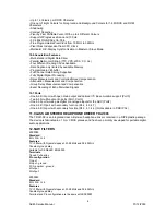
Page 8: ...ecoding of Echo Disturbed Signals 10 7 Ports One 8 bit I O port with open drain output and optional I2 C Bus emulation support Port0 Two 8 bit multifunction I O ports Port1 Port3 One 4 bit port working as digital or analogue inputs for the ADC Port2 One 2 bit I O port with secondary function P4 2 4 3 4 7 One 4 bit I O port with secondary function P4 0 4 1 4 4 Not available in P SDIP 52 11 CLASS AB...

Page 9: ...ation making it essentially blow out proof The LM317 serves a wide variety of applications including local on card regulation This device can also be used to make a programmable output regulator or by connecting a fixed resistor between the adjustment and output the LM317 can be used as a precision current regulator 13 1 2 Features Output Current in Excess of 1 5 A Output Adjustable between 1 2 V ...

Page 10: ... includes versions for processing the multi channel television sound MTS signal conforming to the standard recommended by the Broadcast Television Systems Committee BTSC The DBX noise reduction or alternatively MICRONAS Noise Reduction MNR is performed alignment free Other processed standards are the Japanese FM FM multiplex standard EIA J and the FM Stereo Radio standard Current ICs have to perfo...

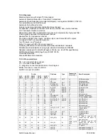
Page 11: ... circuit diagram DVSS if not used connect to DVSS AHVSS connect to AHVSS Pin No Pin Name Type Connection if not used Short Description PLCC 68 pin PSDIP 64 pin PSDIP 52 pin PQFP 80 pin PLQFP 64 pin 1 16 14 9 8 ADR_WS OUT LV ADR word strobe 2 NC LV Not connected 3 15 13 8 7 ADR_DA OUT LV ADR Data Output 4 14 12 7 6 I2S_DA_IN1 IN LV I 2 S1 data input 5 13 11 6 5 I2S_DA_OUT OUT LV I 2 S data output 6...

Page 12: ...T output 2 left 51 33 27 33 25 SC2_OUT_R OUT LV SCART output 2 right 52 32 NC LV Not connected 53 32 31 24 NC LV Not connected 54 31 26 30 23 DACM_SUB OUT LV Subwoofer output 55 30 29 22 NC LV Not connected 56 29 25 28 21 DACM_L OUT LV Loudspeaker out left 57 28 24 27 20 DACM_R OUT LV Loudspeaker out right 58 27 23 26 19 VREF2 X Reference ground 2 59 26 22 25 18 DACA_L OUT LV Headphone out left 60...

Page 13: ...erface 64 pin PSDIP package 13 4 3 Pin Connections and short descriptions NC not connected LV if not used leave vacant X obligatory connect as described in circuit diagram IN Input OUT Output SUPPLY Supply Pin Pin no PSDIP 64 pin Pin name Type Connection if not used Short description 1 TEST IN GNDD Test Input 2 RESQ IN X Reset Input 3 SCL IN OUT X I2 C Bus Clock 4 SDA IN OUT X I 2 C Bus Data 5 GND...

Page 14: ...age Top Video ADC 58 VSUPAF SUPPLY X Analog Supply Voltage 5 0V Frontend 59 VOUT OUT LV Analog Video Output 60 CIN1 IN VRT Analog Chroma 1 Input 61 VIN1 IN VRT Analog Video 1 Input 62 VIN2 IN VRT Analog Video 2 Input 63 VIN3 IN VRT Analog Video 3 Input 64 VIN4 IN VRT Analog Video 4 Input 13 5 TEA6415C 13 5 1 General Description The main function of the IC is to switch 8 video input sources on 6 ou...

Page 15: ... 5Vpp Min 4 5Vpp 19 Ground 20 Input Max 2Vpp Input Current 1mA Max 3mA 13 6 STV9379FA 13 6 1 Description Designed for monitors and high performance TVs the STV9379FA vertical deflection booster can handle flyback voltage up to 90V Further to this it is possible to have a flyback voltage which is more than the double of the supply Pin 2 This allows to decrease the power consumption or to decrease t...

Page 16: ...ain adjustable voltages and currents 13 8 2 Features Output Current Up To 1 5 A Output Voltages of 5 5 2 6 8 8 5 9 12 15 18 24V Thermal Over load protection Short Circuit Protection Output Transition SOA Protection 13 9 AT24C08 13 9 1 Description The AT24C01A 02 04 08 16 provides 1024 2048 4096 8192 16384 bits of serial electrically erasable and programmable read only memory EEPROM organized as 12...

Page 17: ...xt data can also be used for customer defined on screen displays Internal XRAM consists of up to 16 Kbytes Device has an internal ROM of up to 128 KBytes ROMless versions can access up to 1 MByte of external RAM and ROM The SDA 55XX supports a wide range of standards including PAL NTSC and contains a digital slicer for VPS WSS PDC TTX and Closed Caption an accelerating acquisition hardware module ...

Page 18: ...and ROM Characters Shadowing Contrast Reduction Pixel by Pixel Shiftable Cursor With up to 4 Different Colours Support of Progressive Scan and 100 Hz 3 X 4Bits RGB DACs On Chip Free Programmable Pixel Clock from 10 MHz to 32MHz Pixel Clock Independent from CPU Clock Multinorm H V Display Synchronization in Master or Slave Mode Acquisition Features Multistandard Digital Data Slicer Parallel Multi n...

Page 19: ...led Quick OVP 2 ISENSE The Current Sense pin senses the voltage developed on the series resistor inserted in the source of the power MOSFET When I sense reaches 1V the Driver output pin 5 is disabled This is known as the Over Current Protection function A 200mA current source is flowing out of the pin 3 during the start up phase and during the switching phase in case of the Pulsed Mode of operatio...

Page 20: ...nt of CTR G Leadform 10 16 mm provides creepage distance 8 mm for TCET2100 TCET4100 optional suffix letter G is not marked on the optocoupler Coupling System U 13 13 TDA9885T 13 13 1 General Description The TDA9885 is an alignment free single standard without positive modulation vision and sound IF signal PLL 13 13 2 Features 5 V supply voltage Gain controlled wide band Vision Intermediate Frequen...

Page 21: ...tput TOP 9 tuner AGC TakeOver Point TOP SDA 10 I2 C bus data input output SCL 11 I2 C bus clock input SIOMA 12 sound intercarrier output and MAD select n c 13 not connected TAGC 14 tuner AGC output REF 15 4 MHz crystal or reference input VAGC 16 VIF AGC for capacitor note 1 CVBS 17 video output AGND 18 analog ground VPLL 19 VIF PLL for loop filter VP 20 supply voltage 5 V AFC 21 AFC output OP2 22 ...

Page 22: ...ntire service menu parameters of AK45 CHASSIS are listed below 14 2 ADJUST MENU Select the parameter by pressing up down buttons Adjust the parameter by pressing Left Right buttons In ADJUST menu changed values are stored automatically White Point Red White Point Green White Point Blue Not used AGC Apply PAL BG signal VHF 3 Channel 12 and 60dBµV signal level Adjust AGC Automatic Gain Control item ...

Page 23: ...al blank stop position Angle Change Angle by pressing Left Right buttons till the vertical lines of the crosshatch pattern become completely perpendicular to horizontal lines without any angle of vertical deviation Check and readjust ANGLE item if the adjustment becomes improper after some other geometric adjustments are done Bow Change Bow by pressing Left Right buttons till the vertical lines es...

Page 24: ...e vertical amplitude of regular mode REGULAR VERT_SCOR Regular mode Vertical S Correction It s used to adjust the vertical s correction of regular mode REGULAR VERT_SSYM Regular mode Vertical S Symmetry It s used to adjust the vertical s symetry of regular mode REGULAR TRAPEZE Regular mode Trapeze Change Trapezium by pressing Left Right buttons till vertical lines especially lines at the sides of ...

Page 25: ... mode PANORAMIC HORZ_AMPL Panoramic mode Horizontal amplitude It s used to adjust the horizontal amplitude of panoramic mode 14 9 ZOOM VERT_POS 14 9 Zoom mode Vertical Position It s used to adjust the vertical position of 14 9 zoom mode 14 9 ZOOM VERT_AMPL 14 9 Zoom mode Vertical Amplitude It s used to adjust the vertical amplitude of 14 9 zoom mode 14 9 ZOOM VERT_SCOR 14 9 Zoom mode Vertical S Co...

Page 26: ...LE VERT_POS 16 9 Zoom Subtitle mode Vertical position It s used to adjust the vertical position of 16 9 zoom subtitle mode 16 9 ZOOM SUBTITLE VERT_AMPL 16 9 Zoom Subtitle mode Vertical amplitude It s used to adjust the vertical amplitude of 16 9 zoom subtitle mode 16 9 ZOOM SUBTITLE VERT_SCOR 16 9 Zoom Subtitle mode Vertical S Correction It s used to adjust the vertical s correction of 16 9 zoom s...

Page 27: ...NCE WDR RED NORMAL The amplitude of R of RGB output can be adjusted with the drive parameter WDR for the colour temperature of normal mode REFERENCE WDR GREEN NORMAL The amplitude of G of RGB output can be adjusted with the drive parameter WDR for the colour temperature of normal mode REFERENCE WDR BLUE NORMAL The amplitude of B of RGB output can be adjusted with the drive parameter WDR for the co...

Page 28: ...DR BLUE WARM The amplitude of B of RGB output can be adjusted with the drive parameter WDR for the colour temp of cool mode STANDARD MODE BRIGHTNESS It s used to adjust the brightness value of standard mode STANDARD MODE COLOUR It s used to adjust the colour value of standard mode STANDARD MODE CONTRAST It s used to adjust the contrast value of standard mode FULL VERT_POS 16 9 MODE It s used to ad...

Page 29: ...SS It s fixed PERSONAL MODE FACTORY SETTING COLOUR It s fixed PERSONAL MODE FACTORY SETTING CONTRAST It s fixed SCINC FOR PANAROMIC MODE scaler1 coefficient this scaler is compressing the signal SCINC1 FOR PANAROMIC MODE scaler2 coefficient this scaler is expanding the signal VOLUME AFTER APS It s used to adjust the volume level after APS VERTICAL SCROLL It s used to adjust the step width for scro...

Page 30: ... signals 16 9 RGB HORIZANTOL AMPLITUDE It s used to adjust the horizontal amplitude in 16 9 mode for RGB signals 16 9 SUBTITLE RGB HORIZONTAL AMPLITUDE It s used to adjust the horizontal amplitude in 16 9 subtitle mode for RGB signals FULL RGB HORIZONTAL AMPLITUDE It s used to adjust the horizontal amplitude in full mode for RGB signals TELETEXT HORZ_POS It s used to adjust the horizontal position...

Page 31: ...tube for 4 3 mode adjustment 021 042 019 4 3 Horz Blank Stop It will be used only at 16 9 tube for 4 3 mode adjustment 140 175 020 EHTV compensation 054 066 021 EHTTM compensation 004 001 022 EHTEW compensation 219 160 023 WDR 024 WDG 025 WDB 026 CR 027 CG 028 CB VIDEO PROCESSOR ADJUSTS ITSELF 029 COR coring level 015 031 030 REGULAR VERT_POS Vertical Position 128 129 031 REGULAR VERT_AMPL Vertica...

Page 32: ...YM 162 077 16 9 ZOOM SUBTITLE HOR_CORNER 081 078 16 9 ZOOM SUBTITLE HORZ_POS 035 079 16 9 ZOOM SUBTITLE HORZ_AMPL 021 080 OSD Position 217 205 081 BCLTHR Beam current threshold 050 060 082 BCLG Beam current loop gain 008 007 083 ROTATION TILT 000 000 084 LSLSA Luma soft limiter 000 003 085 LSLSB Luma soft limiter 000 000 086 LSL2 Luma soft limiter 255 255 087 LSLTA Luma soft limiter 000 000 088 LS...

Page 33: ...ODE FACTORY SETTING BRIGHTNESS 027 043 127 PERSONAL MODE FACTORY SETTING COLOUR 050 050 128 PERSONAL MODE FACTORY SETTING CONTRAST 030 032 129 SCINC FOR PANORAMIC MODE 032 056 130 SCINC1 FOR PANORAMIC MODE 032 125 131 VOLUME AFTER APS 005 132 VERTICAL SCROLL 005 008 133 14 9 HORIZONTAL START It will be used only at 16 9 tube for 14 9 mode adjustment 031 134 14 9 HORIZONTAL STOP It will be used onl...

Page 34: ...Pin 34 3 58 1 2 or 3 crystals Pin 35 No crystal 1 0 Pal BG Pal DK Pal I I Secam BG Secam DK Secam L L Secam K1 Pin 34 No crystal Pin 35 4 43 1 crystal 1 1 Pal BG Pal DK Pal I I Secam BG Secam DK Secam L L Secam K1 Pal M Pal N Ntsc M Pin 34 3 58 1 2 or 3 crystals Pin 35 4 43 1 crystal Option 1 0x01 Video Processor Decoder Mode Register B7 x x B6 x x B5 x x B4 x x B3 x x B2 x x B1 x x B0 x x Option ...

Page 35: ... 0 choice for others country option 1 BG 0 DK Option 4 B7 x x B6 x x B5 x x B4 x x B3 x x B2 x x B1 x x B0 x x Option 5 CTI Avaliable Mono AVL B7 x x B6 x x B5 x x B4 x x B3 x x B2 x x B1 x x B0 x x Option 6 B7 TEXT LANGUAGE 3 B6 TEXT LANGUAGE 2 B5 TEXT LANGUAGE 1 B4 x x B3 x x B2 x x B1 x x B0 x x Option 7 OPTIONHOTELACTIVE PLL_VST PIP Zoom Mode PIP Position B7 x x B6 x x B5 F note 1 B4 x x B3 x ...

Page 36: ...ndard Tuner note 4 IfD 1 IF DK 38 0 MHz 0 IF DK 38 9 MHz note 5 IfM 1 IF M N 45 75 MHz S N American Models Tuner UV1336 Only Pal M N Ntsc M 0 IF M N 38 9 MHz Euro M N Models Standard Tuner Note 6 Aps Only for PLL 0 A P S done 1 A P S set note 7 Hp Headphone available 0 No headphone 1 Headphone available note 8 Hue Hue Available 0 No Hue 1 Hue available Option 9 Standard Available B7 NM note 1 B6 P...

Page 37: ...1 Back SVHS available Option 11 PLL Tuner Control 1 Byte Pll tuner control 1 byte b7 b6 b5 b4 b3 b2 b1 b0 Philips UV1316T MK3 1 0 0 0 1 1 1 0 Philips UV1316MK2 1 0 0 0 1 1 1 0 Alps TELE9X062A 1 0 0 0 1 1 1 0 Samsung TEXX2949PG28A 1 0 0 0 1 1 1 0 Siel PT060 1 0 0 0 1 1 1 0 Temic 5001PH5 3X0003 1 0 0 0 1 1 1 0 Thomson CTT5020 1 0 0 0 1 1 1 0 Option 12 PLL Tuner Control 2 Low Byte Pll tuner control 2...

Page 38: ...0 Siel PT060 0 0 0 0 1 0 1 0 Temic 5001PH5 3X0003 0 0 0 0 0 0 0 0 Thomson CTT5020 1 0 1 0 1 0 1 0 AA hex Option 16 PLL Tuner VHF LOW VHF HIGH Crossover High Byte Pll tuner VHF LOW VHF HIGH crossover high byte b7 b6 b5 b4 b3 b2 b1 b0 Philips UV1316T MK3 0 0 0 0 1 1 0 0 Philips UV1316MK2 0 0 0 0 1 1 0 0 0C hex Alps TELE9X062A 0 0 0 0 0 0 0 0 Samsung TEXX2949PG28A 0 0 0 0 1 1 0 1 Siel PT060 0 0 0 0 1...

Page 39: ...2949PG28A 0 0 0 0 0 0 1 0 Siel PT060 1 1 0 1 0 0 0 0 Temic 5001PH5 3X0003 0 0 0 0 0 1 0 0 Thomson CTT5020 0 0 0 0 0 1 1 0 Option 22 PIP PLL Tuner Control 2 High Byte b7 b6 b5 b4 b3 b2 b1 b0 Philips UV1316MK2 0 0 1 1 0 1 0 0 Alps TELE9X062A 0 0 0 0 1 0 0 0 Samsung TEXX2949PG28A 0 0 0 0 1 0 0 0 Siel PT060 0 0 1 1 0 0 0 0 Temic 5001PH5 3X0003 0 0 0 0 0 0 0 1 Thomson CTT5020 1 0 0 0 0 1 0 1 Option 23 ...

Page 40: ...0 0 0 0 0 0 0 Thomson CTT5020 0 0 0 1 1 0 1 1 1B hex Option 27 Language Available 1 B7 L7 DANISH B6 L6 SWEDISH B5 L5 ITALIAN B4 L4 PORTUGUESE B3 L3 SPANISH B2 L2 FRENCH B1 L1 GERMAN B0 L0 ENGLISH 1 Language available 0 Language not available Option 28 Language Available 2 B7 L15 CROATIC B6 L14 POLISH B5 L13 SLOVAK B4 L12 CZECH B3 L11 HUNGARY B2 L10 GREEK B1 L9 TURKEY B0 L8 NORWEGIAN 1 Language ava...

Page 41: ... CH 0 0 1 0 0 I 0 0 1 0 1 F 0 0 1 1 0 RSM 0 0 1 1 1 B 0 1 0 0 0 DK 0 1 0 0 1 S 0 1 0 1 0 N 0 1 0 1 1 FIN 0 1 1 0 0 GB 0 1 1 0 1 IRL 0 1 1 1 0 IS 0 1 1 1 1 NL 1 0 0 0 0 E 1 0 0 0 1 P 1 0 0 1 0 PL 1 0 0 1 1 CZ 1 0 1 0 0 H 1 0 1 0 1 HR 1 0 1 1 0 GR 1 0 1 1 1 TR Option 31 Prescaler MSP FM AVL OFF b7 b6 b5 b4 b3 b2 b1 b0 prescaler MSP FM AVL OFF 0 0 0 0 1 0 0 0 b7 b6 b5 b4 b3 b2 b1 b0 prescaler MSP FM ...

Page 42: ... Option 35 Not used B7 x note 7 B6 x note 6 B5 x note 5 B4 x note 4 B3 AV2S Scart2 SVHS B2 Macro Macrovision B1 DP Dolby Prologic B0 VD Virtual Dolby Option 36 Not used B7 x note 7 B6 TAT 1 Tilt and trapez enabled B5 SWF 1 Subwoofer enabled B4 VLO 1 Variable line out B3 VBUS 1 Vestelbus enabled B2 x x B1 DVD 1 DVD enabled B0 DVB 1 DVB enabled Option 37 Reserved for USA Option 38 TV Teletext Mode S...

Page 43: ... Band 1 b7 b6 b5 b4 b3 b2 b1 b0 EQUALIZER BAND 1 0 0 0 0 0 1 1 0 Option 40 Personal Preferance Equalizer Band 2 b7 b6 b5 b4 b3 b2 b1 b0 EQUALIZER BAND 2 0 0 0 0 0 1 1 0 Option 41 Personal Preferance Equalizer Band 3 b7 b6 b5 b4 b3 b2 b1 b0 EQUALIZER BAND 3 0 0 0 0 0 1 1 0 Option 42 Personal Preferance Equalizer Band 4 b7 b6 b5 b4 b3 b2 b1 b0 EQUALIZER BAND 4 0 0 0 0 0 1 1 0 Option 43 Personal Pref...

Page 44: ...b3 b2 b1 b0 3D Panorama 0 0 0 0 1 0 1 1 b7 b6 b5 b4 b3 b2 b1 b0 NICAM Prescale for Dolby 0 0 0 0 1 1 1 0 Note if virtual dolby is available this option is not used Option 52 Scart Input Prescale b7 b6 b5 b4 b3 b2 b1 b0 Scart Input Prescale for Stereo 0 0 0 0 1 0 0 0 b7 b6 b5 b4 b3 b2 b1 b0 Scart Input Prescale for Dolby 0 0 0 0 1 1 1 1 b7 b6 b5 b4 b3 b2 b1 b0 prescaler MSP Scart AVL OFF 0 0 0 1 1 ...

Page 45: ... available 1 VRS available note 4 CRM CARRIER MUTE OFF ON 0 Sound carrier mute is ON in the Stereo Sound IC 1 Sound carrier mute is OFF in the Stereo Sound IC i e option available note 2 LBE LBE Dynamic Bass 0 LBE not available 1 LBE available note 1 Spa Spatial Efect available 0 Spatial Efect not available 1 Spatial Efect available note 0 Avl Automatic volume level available on the Menu 0 Automat...

Page 46: ...er L7L6L5L4L3L2L1L0 Delay 0 00000000 4 sec 32 00100000 12 sec 1 00000001 4 25 sec 33 00100001 12 25 sec 2 00000010 4 5 sec 34 00100010 12 5 sec 3 00000011 4 75 sec 35 00100011 12 75 sec 4 00000100 5 Sec 36 00100100 13 sec 5 00000101 5 25 Sec 37 00100101 13 25 sec 6 00000110 5 5 Sec 38 00100110 13 5 sec 7 00000111 5 75 Sec 39 00100111 13 75 sec 8 00001000 6 sec 40 00101000 14 sec 9 00001001 6 25 se...

Page 47: ... 9 75 sec 55 00110111 17 75 sec 24 00011000 10 sec 56 00111000 18 sec 25 00011001 10 25 sec 57 00111001 18 25 sec 26 00011010 10 5 sec 58 00111010 18 5 sec 27 00011011 10 75 sec 59 00111011 18 75 sec 28 00011100 12 sec 60 00111100 19 sec 29 00011101 12 25 sec 61 00111101 19 25 sec 30 00011110 12 5 sec 62 00111110 19 5 sec 31 00011111 12 75 sec 63 00111111 19 75 sec ...

Page 48: ...10 11 00001011 43 00101011 12 00001100 44 00101100 13 00001101 45 00101101 14 00001110 46 00101110 15 00001111 47 00101111 16 00010000 48 00110000 17 00010001 49 00110001 18 00010010 50 00110010 19 00010011 51 00110011 20 00010100 52 00110100 21 00010101 53 00110101 22 00010110 54 00110110 23 00010111 55 00110111 24 00011000 56 00111000 25 00011001 57 00111001 26 00011010 58 00111010 27 00011011 5...

Page 49: ...XXXXX XX XXXXXXXX 023 XX XXXXXXXX XX XXXXXXXX XX XXXXXXXX 024 XX XXXXXXXX XX XXXXXXXX XX XXXXXXXX 025 XX XXXXXXXX XX XXXXXXXX XX XXXXXXXX 026 XX XXXXXXXX XX XXXXXXXX XX XXXXXXXX 027 FF 11111111 FF 11111111 FF 11111111 028 FF 11111111 FF 11111111 FF 11111111 029 FF 11111111 EF 11101111 EF 11101111 030 XX XXXXXXX XX XXXXXXX XX XXXXXXX 031 0F 00001111 0F 00001111 0F 00001111 032 23 00100011 23 001000...

Page 50: ...10101 75 01110101 055 00 00000000 00 00000000 00 00000000 056 DE 11011110 DE 11011110 DE 11011110 057 19 00011001 19 00011001 19 00011001 058 00 00000000 00 00000000 00 00000000 059 64 01100100 64 01100100 64 01100100 060 10 00010000 10 00010000 10 00010000 ...

Page 51: ... 14 5 SCREEN ADJUSTMENT FBT SCREEN From the option list change option 2 bit 6 from 0 to 1 for disabling vertical scan Adjust horizontal line via screen adjust pot as thin as possible Then press 0 to leave service menu SCREEN ADJUST POT ...

Page 52: ...48 AK45 Service Manual 01 12 2003 14 6 GEOMETRY ADJUSTMENT 4 3 FORMATS 4 3 MODE 16 9 MODE ...

Page 53: ...49 AK45 Service Manual 01 12 2003 16 9 FORMATS AUTO MODE ...

Page 54: ...50 AK45 Service Manual 01 12 2003 REGULAR MODE ...

Page 55: ...51 AK45 Service Manual 01 12 2003 ZOOM 14 9 MODE ...

Page 56: ...52 AK45 Service Manual 01 12 2003 ZOOM 16 9 MODE ...

Page 57: ...53 AK45 Service Manual 01 12 2003 SUBTITLE ZOOM MODE ...

Page 58: ...54 AK45 Service Manual 01 12 2003 FULL MODE ...

Page 59: ...55 AK45 Service Manual 01 12 2003 PANOROMIC MODE ...

Page 60: ...56 AK45 Service Manual 01 12 2003 ...

Page 61: ...TOM 2845 6 7W 11 60000011 EPS 12 20110272 MD ASY LD05 LED BOARD 2845 45W 14 30000295 CAP CER 100NF 50V Z F C100 15 30002325 CNAS 2P 600 TB FLT W C UL2468AWG24 PL101 16 30002335 CNAS 3P 600 PREAMP FLT W C UL2468AWG24 PL102 17 30007720 IC PREAMPLIFIER TSOP1836 36kHz 5V MD100 18 30010688 LED RED GREEN VDC30354 3MM D100 19 30019922 PCB 11LD05 1 20 20114820 BUTTON ASSY 2845 45W SILVER P 21 20099579 LEN...

Page 62: ...TOP GREEN SD PL107 45 30001891 RCA JACK 1P WHITE 28 FAV JK102 46 30001892 RCA JACK 1P RED 28 FAV JK103 47 30001893 RCA JACK 1P YELLOW 28 FAV JK101 48 30002362 CNAS 830 FAV SHL W 4C FER PL106 50 30001902 JACK HEADPHONE STEREO WO SW JK108 51 30020926 CNAS 3P 900 FLT W BLK C UL2468AWG24 PL108 53 30002181 SWITCH TACT 4 SW101 SW102 SW103 SW104 SW105 54 30002302 CNAS 6P 450 TB FLT W C UL2468AWG24 PL109 ...

Page 63: ...1 30017085 LINEARITY COIL 20UH L602 92 30021290 TRF FBT SAFE 110 50HZ LAYER TR600 96 30002183 RELAY SAFE MON15 KI S 212M RL100 98 30001518 IC TDA1308 IC704 99 30001836 CONN HEADER 3P 2 5MM TOP BLACK SD PL711 101 30001830 CONN HEADER 2P 2 5MM TOP BLUE SD PL207 102 30001839 CONN HEADER 3P 2 5MM TOP GREEN SD PL703 103 30009834 CABL 1P 60 SIS B B 105 30010921 DOUBLE DECK SCART SOCKET PL204 107 3001365...

Page 64: ...Y 3 6 04 M3 137 35000183 SCREW C ZN YSMB M3 12 138 35006411 HEATSINK AK45 VERTICAL 139 40000020 TR HOLDER TR 06A 140 40000146 INSULATOR SILICON PAD 15 20 141 40011922 EDGE SADDLE CT 16 142 20113526 HE ASY 45 AUDIO W CABLE HOLDER 143 30016113 IC AAMP TDA7269A 2 14W MULTIWATT11 IC301 144 35000158 NUT C ZN BOTTOM M3 145 35000165 KNURL WASHER C ZNSY 3 6 04 M3 146 35000182 SCREW C ZN YSMB M3 10 147 350...

Page 65: ...AP EL 1000UF 25V M C148 C613 C614 174 30000402 CAP EL 47UF 100V M C603 175 30000406 CAP EL 47UF 250V M HR 105 C125 C605 176 30000409 CAP EL 470UF 25V M C608 C809 177 30000440 CAP CER SAFE 2 2NF 4KV M C161 C115 179 30001134 RES MO 2W 2 2R J R640 180 30001224 RES FUSE SAFE 1 2W 0 22R J R152 181 30001270 PTC SAFE 9 OHM TH100 182 30001299 DIODE UF5404 3A 400V 150A D603 D604 183 30001320 DIODE GUC BY22...

Page 66: ... 35000135 TEST PIN 1 1MM PL214 211 40006432 MOUNTING BUTTON MB 10 212 70000029 SOLDER INGOT 63 37 213 70000030 SOLDER WIRE CAP 1 00mm 60Sn40Pb 215 30001705 FILTER SAW OFWG9353M Z201 216 30015591 FILTER SAW G3967 Z200 218 20000848 FUSE ASSY TK79 A 2 5A F100 219 30001731 FUSE SAFE 2 5A 250V 5 20MM 220 35000136 FUSE HOLDER TK79 A GRAY 222 20132938 MB M 45 SMPS170 270VWO D D S WO P 24 5 8 223 20070614...

Page 67: ...0 30000352 CAP EL 100UF 16V M C776 C782 271 30000362 CAP EL 1UF 50V M C784 273 30001971 FERRITE BEAT 805 BLM21A601S L714 L715 274 30012581 CAP SMD 1NF 50V K R 0603 C706 C715 C779 C786 275 30012585 CAP SMD 2 2NF 50V K R 0603 C775 C785 C795 C796 276 30012641 RES SMD 1 16W 10K J 0603 R747 R756 277 30012692 RES SMD 1 16W 4 7K J 0603 R742 R746 278 30012709 RES SMD 1 16W 7 5K J 0603 R749 R754 279 300161...

Page 68: ...7 RES SMD 1 16W 1K J 0603 R318 334 30012713 RES SMD 1 16W 75R J 0603 R215 R200 R236 R205 R310 R201 336 30016126 CAP SMD 220NF 16V K R 0603 C234 C210 C208 C217 C214 C215 C222 C209 337 30016654 CAP SMD 100NF 16V K R 0603 C231 340 30001288 DIODE BYV27 200 2A 200V 50A D110 341 30001315 DIODE BYD33D 1A 200V 20A D127 342 30000090 CAP MKT 22NF 100V J C119 350 30000452 RES CF 1 4W 10R J R108 351 30000459 ...

Page 69: ...01344 DIODE ZENER 6 2V 1 2W D106 382 30001377 DIODE ZENER 33V UZT 33B D601 383 30001979 FIXED COIL 1UH Q45 M A L206 L207 L263 L264 L717 L265 384 30001987 FIXED COIL 4 7UH Q70 K A L266 385 30001992 FIXED COIL 10UH Q65 K A L103 L504 L500 L505 L501 L502 L503 386 30001996 FIXED COIL 22UH Q40 K L700 L711 L701 L203 L702 L703 J344 387 30003722 DIODE ZENER ZPD15V D133 388 30015222 RES MO 1W 0 75R J R140 3...

Page 70: ...31 IC116 IC601 417 30006940 CAP CER 2 7NF 1KV K B C113 418 30007308 CAP CER 220PF 1KV K PULSE C111 C118 C120 C122 419 30007708 CAP CER 1NF 1KV K PULSE C162 420 30009208 CAP CER 470PF 1KV K PULSE C114 C636 421 30000480 RES SMD 1 10W 100K J 0805 R144 R625 R627 422 30000494 RES SMD 1 10W 120R J 0805 R162 423 30000575 RES SMD 1 10W 2K J R134 424 30000593 RES SMD 1 10W 2 2K J 0805 R139 R164 R106 R259 R...

Page 71: ...738 C722 447 30012579 CAP SMD 82PF 50V J 0603 C333 448 30012581 CAP SMD 1NF 50V K R 0603 C149 C732 C258 C267 C745 C793 C749 C712 C349 C713 C794 C728 C359 C360 C353 449 30012583 CAP SMD 1 5NF 50V K 0603 C748 C731 C702 C237 450 30012584 CAP SMD 1 8NF 50V K R 0603 C635 451 30012585 CAP SMD 2 2NF 50V K R 0603 C282 C260 C284 452 30012586 CAP SMD 22NF 50V K 0603 C246 C248 453 30012588 CAP SMD 33NF 50V K...

Page 72: ...0012677 RES SMD 1 16W 3 3K J 0603 R261 476 30012679 RES SMD 1 16W 3 9K J 0603 R526 R277 R590 R550 R527 R524 R415 R521 R819 477 30012685 RES SMD 1 16W 33K J 0603 R533 478 30012692 RES SMD 1 16W 4 7K J 0603 R127 R153 R554 R129 R516 R522 R343 R404 R624 R626 R211 479 30012695 RES SMD 1 16W 470R J 0603 R553 R700 R701 R607 R416 R417 R418 R419 R420 R421 R422 R423 R424 R426 R425 R793 R794 480 30012696 RES...

Page 73: ...58 TR BC858B SMD Q513 513 30012510 RES SMD 1 16W 100R J 0603 R565 R561 514 30012641 RES SMD 1 16W 10K J 0603 R587 R585 R586 R588 515 30012641 RES SMD 1 16W 10K J 0603 R566 516 30012692 RES SMD 1 16W 4 7K J 0603 R564 521 30000872 RES MF 1 4W 120K F R631 522 30000927 RES MF 1 4W 220K J R605 523 30001162 RES MO 1W 390R J R639 524 30001244 RES FUSE SAFE 1 2W 0 47R J R614 R611 530 30016126 CAP SMD 220N...

Page 74: ... C932 568 30000407 CAP EL 470UF 16V M C915 569 30000438 CAP CER 2 2NF 2KV C908 570 30001427 TR BF422 Q900 571 30001452 TR BC327 Q906 572 30014346 IC 78L05 TO 92 100mA IC902 573 30014346 IC 78L05 TO 92 100mA IC901 574 30000294 CAP SMD 100NF 50V K 0805 C910 C913 C921 575 30001285 DIODE 1N4148 SMD D910 576 30001285 DIODE 1N4148 SMD D909 577 30001458 TR BC858B SMD Q901 Q902 Q903 Q904 Q905 578 30012510...

Page 75: ... 1 10W 1 5R J 0805 R106 607 30002735 IC SAA3010T IC1 608 30012510 RES SMD 1 16W 100R J 0603 R101 609 30012641 RES SMD 1 16W 10K J 0603 R104 610 30012696 RES SMD 1 16W 47K J 0603 R105 611 30012705 RES SMD 1 16W 6 8K J 0603 R100 612 30012986 RES SMD 1 16W 68R J 0603 R103 613 30013001 RES SMD 1 16W 1K F 0603 R102 614 30020343 PCB 11UK10 2 615 30000395 CAP EL 47UF 6 3V M 4 7MM C100 616 30001452 TR BC3...

Page 76: ...U BAZLI L8341413 639 20144925 EXP KIT AK37 2845 46 45W 46W V 0 640 20004520 CABLE HOLDER DX15 I 641 60000991 KIRMA HDPE 642 20084045 STRAP TIE L 118 643 60000018 COPOLYMER POLYPROPYLENE 644 20085269 CABLE HOLDER CRT I UL94V 0 645 60000855 KIRMA FR ABS BLUE CRT 646 40006731 ISOLATION COTTON 9x25000mm 647 70000331 ADHESIVE TAPE 75MM 660M 4125 648 20144927 SCR ASSY 2845W 6W 7W SB AK45 V 0 649 2012011...

Page 77: ... SPEAKER 8R 15W 57 160 improved 666 50011720 LABEL HIGH END 667 20150150 SPK AS 2990 XX W TWT AK45 L 668 30000426 CAP EL 6 8UF 50V M BPL 669 30001947 TWEETER 8R 15W CLOSED 670 30002238 CABL 2P 200 SPK DIS UL1672AWG24 671 30013903 CNAS 2P 900 DIS W C FER UL2547 AWG24 672 30028092 SPEAKER 8R 15W 57 160 improved 673 50011720 LABEL HIGH END 674 30008915 28 CPT TUBE SAFE 16 9 SF IRON 675 40001939 LOGO ...

Page 78: ...A SCL SC1 SC2 IF SVHS Y EXT_CVBS Y SC2_V_OUT TO_PIP SC1_RGB SC2_RGB DVD DVB PIP R G B FB CVBS R G B FB SCL SDA SYNC SC3 R G B Horizontal Vertical Stage STV9379FA Yoke CRT RGB AMPLIFIER TDA 6107 PHILIPS R G B QSS MSP34XXG SCL SDA SC1 SC2 FRONT SC3 TDA1308 L R Headphone TDA7269A AUDIO AMPLIFIER L R 8 ohm 12W 8 ohm 12W SDA5555 MicroController 24CO8 E2PROM SDA SCL TV_LINK CVBS_TEXT OSD_R OSD_G OSD_B O...

Page 79: ...58 JVC AK45 Service Manual 01 12 2003 17 CIRCUIT DIAGRAMS 11AK45B5 1 ...

Page 80: ...59 JVC AK45 Service Manual 01 12 2003 11AK45B5 2 ...

Page 81: ...60 JVC AK45 Service Manual 01 12 2003 11AK45B5 3 ...

Page 82: ...61 JVC AK45 Service Manual 01 12 2003 11AK45B5 4 ...

Page 83: ...62 JVC AK45 Service Manual 01 12 2003 11AK45B5 5 ...

Page 84: ...63 JVC AK45 Service Manual 01 12 2003 11TP45B 1 ...

Page 85: ...64 JVC AK45 Service Manual 01 12 2003 11SB107 4 ...

Page 86: ...65 JVC AK45 Service Manual 01 12 2003 11SW01 3 ...

Page 87: ...66 JVC AK45 Service Manual 01 12 2003 11LD13 ...

Page 88: ......

Page 89: ......

Page 90: ......

Page 91: ......

Page 92: ......

Page 93: ......

Page 94: ......

Page 95: ......

Page 96: ......

Page 97: ......

Page 98: ......

Page 99: ......

Page 100: ......

Page 101: ......

Page 102: ......

Page 103: ......

Page 104: ......

Page 105: ......

Page 106: ......

Page 107: ......

Page 108: ......

Page 109: ......

Reviews: