background image

Summary of Contents for MV-3010

Page 1: ...E T e pct y orte Pr PIE TAS NG UN V3oS 1 SIMAK TO TEAC 77 MV 3010 _ Service Manual...

Page 2: ...SEMBLY ATTACHMENT ttt MA 10 7 RG POST HEIGHT ADJUSTMENT a eed iibiides MA 11 PERIODIC niono den pobe Ia ansa ak Vaska MA 12 EXPLODED VIEW OF THE CASSETTE DECK MECHANISM enn MA 14 MECHANICAL PARTS LIST...

Page 3: ...cking capacitors noise blocking filters etc 3 Use specified internal wiring Note especially Wires covered with PVC tubing Double insulated wires High voltage leads 4 Use specified insulating materials...

Page 4: ...ake care not to short circuit nearby components 2 Playback the test tape and allow the automatic ATR to finish 3 Connect the lead attached in step 1 to the Tuner ETAO1 earth line Make sure that the le...

Page 5: ...pe entrance adjustment screw Q FM Waveform Envelope exit adjustment screw Q Audio Azimuth adjustment screw Control Head phase X value adjustment point Audio CTL Head height adjustment screw Head tilt...

Page 6: ...Connected to the rotating head drum and drives the rotating The cassette is loaded and ejected via the drive from the capstan motor B Detection of completed cassette insertion operation head This isd...

Page 7: ...t to adjust gap A and gap B so that they are the same Loading Block Rail Groove Tension Arm BT Band Ass y Reel Ass y H BT adj a 0 2 o 2 I Lu reduce the gap BT torque reduction insert into e To increas...

Page 8: ...eck 1 Reference line Audio CTL Head Adjustment 1 Using an ordinary cassette tape set to CUE mode Drum npa B Drim Gugut 2 Turn screw and adjust for smooth transport at the take up guide Tape Transport...

Page 9: ...the supply guide roller and take up guide roller Make sure that there are no or wrinkles as shown in the figure below Turn with a e incorrect Gorset e standard screwdriver roller Guide Roller Tight Sc...

Page 10: ...adjusting 5 1 PRELIMINARY CHECKS 1 FM Envelope Waveform Check 1 Connect the CH 1 oscilloscope to TP of PB ENV and CH 2 to TP of CTL At this time trigger the oscilloscope externally with the signal RF...

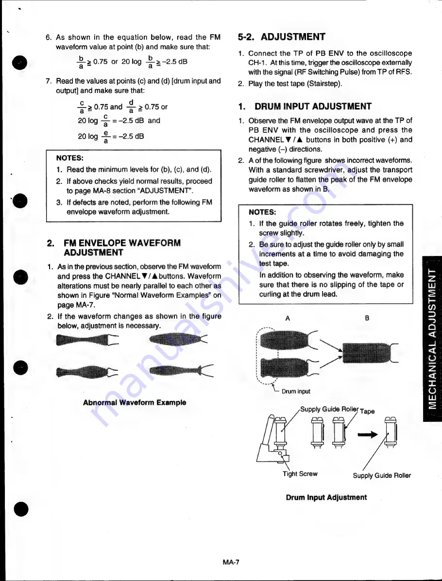
Page 11: ...form Example 5 2 ADJUSTMENT MA 7 1 Connect the TP of PB ENV to the oscilloscope CH 1 Atthis time trigger the oscilloscope externally with the signal RF Switching Pulse from TP of RFS Play the test tap...

Page 12: ...inkling 5 3 INTERCHANGEABILITY occurs at the take up guide adjust by turning screw ADJUSTMENT of the Audio CTL Head as shown in the figure below 1 Observe the FM envelope output waveform at the oscill...

Page 13: ...EIGHT AZIMUTH AND SLANT Refer to 3 2 MA 4 for details regarding AUDIO CTL HEAD HEIGHT AND AZIMUTH ADJUSTMENT MA 9 5 5 SETSCREW TIGHTENING 1 Check for maximum FM output waveform maximum audio output an...

Page 14: ...y Gear Now twist the FD Pinion Gear until it stops The assembly should now resemble Fig 2 FD Gear Case FD Relay Gear FD Gear Case FD Pinion Gear re Fig 4 MD Rear View FD Face Gear 5 Twist the FD Pinio...

Page 15: ...Take up Guide 1 Use a blank tape and set the VCR to REV mode 2 Twist screw E and adjust the RG Post height until the tape is aligned with the lower winding plunger MA 11 2 o 2 2 I...

Page 16: ...dust particles allowed to accumulate dust may lead to damage to the video tape and above parts 3 After cleaning with alcohol allow the parts to dry thoroughly before using a cassette tape NOTE When c...

Page 17: ...0 Cylinder Ass y Clutch Ass y Drive Belt BT Band Ass y Soft Brake Ass y T Main Brake Ass y S Main Brake Ass y Pinch Roller Arm Ass y Audio CTL Head T Reel Ass y S Reel Ass y Capstan Motor Ass y Loadin...

Page 18: ...o 2 I LLI x 0 o LL LLI m O n Lu W2r212...

Page 19: ...SS Y FPC4 CONNECTOR C TAMS SCREW TAPPING S 2 6X6 DRUM EARTH ASS Y TAPPING SCREW 2 6X4 MOTOR E20XL15 TAMS SCREW 2 6X15 ROTOR SCREW B ASS Y TAPPING SCREW 3 0X5 F POST METAL ASS Y TAPE GUIDE ASS Y CASSET...

Page 20: ...ASHER 2 5X5X0 3 PINCH ROLLER ARM ASS Y CAPSTAN MOTOR F2QTB10 TAPPING SCREW 2 6 6 C BRAKE ASS Y POLYSLIDER WASHER C 2 1X5X0 5 C BRAKE SPRING TENSION ARM ASS Y BT ARM METAL BT SPRING BT LEVER POLYSLIDER...

Page 21: ...01 62D80651509 62080651510_ 620806516301 620980326051 6209 0426051 620806517501 62080651703 62080651704 62080651705 Description TAMS SCREW 2 6X5 CAM DRIVE GEAR WORM WHEEL OPEN ANGLE AH ADJUST NUT OPTI...

Page 22: ...MOTOR DRIVER 1 601 72915 VPS ICEO1 SDA5642 LINE TUCONTROL 5 VIDEO Q A V SW CONTROL 22 oo MODF SW SERIAL SER PICTURE CONTROL VIDEO IN S YIC PROCESS E duds 1C201 LA7437 DETA 5 AUDIO IN CD4052BE AUDIO O...

Page 23: ...Circuit Ref Number Head Name Tolerance 1 96 2 96 x5 No Mark 10 2096 No Connection Resistance 10 x 10 1000 ohms Carbon Resistor 1 6W Circuit Ref Number Head Name Resistance 1 1 ohm Decimal Point Mark...

Page 24: ...rimmer Capacitor Ceramic Capacitor F Type CH Ceramic Capacitor CH Type LH Ceramic Capacitor LH Type RH Ceramic Capacitor RH Type SH Ceramic Capacitor SH Type Chip Resistor 2125 Type TH Ceramic Capacit...

Page 25: ...ENTIFICATION TYPE NUMBER 2SC2458T Y GR RN1203 TPE4 DTA124EST 2SA1048 GR TA7291S B AT24C01A AT24C02 2SC4517 TA76431S 2SD1581 2SD2132T VW 2SC1959T GR CD4052BE PST9129T LC89970 LA7411 LA7156 PH530090 LA7...

Page 26: ...CXP88140 XXXQ...

Page 27: ...5 ELECTRICAL PARTS LOCATION PC BOARD ASS Y MAIN 1 14 2 RN 3...

Page 28: ...PC BOARD ASS Y MAIN MAIN 180562111...

Page 29: ...PC BOARD ASS Y HEAD PC BOARD ASS Y SUB 1 TANS 121295081 PLQ 1815 10...

Page 30: ...emove the Bracket G Remove the Sub PCB if one is attached from the Main PCB Attach the Face Plate with the Dust Cover pushed open 6 2 REMOVING THE DECK MECHANISM Disconnect the Flexible Wire 9P N201 f...

Page 31: ...e three prongs on the chassis Do not hold the Tuner when removing the Main PCB Remove the Sub PCB if one is attached from the Main PCB 7 2 INSTALLING THE DECK MECHANISM FOR BRIEF OPERATION D Attach th...

Page 32: ...8 CABINET EXPLODED VIEW points for the spring M 5 5 c 3 8 2...

Page 33: ...arked refer to pages PL 2 PL 11 DECK MECHANISM 59275 COVER BOTTOM PAL COVER TOP PAL BKT BAR S PLATE AUD REAR PANEL RCA SPACER DECK S SPACER DECK L SPACER DECK 2 FACE PLATE ASS Y 22327020 CHASSIS CUSHI...

Page 34: ...CITOR CHIP 180PF 50V CAPACITOR CHIP 56PF 50V CAPACITOR CHIP 22PF 50V CAPACITOR CHIP 0 01UF 25V CAPACITOR CHIP 7PF 50V CAPACITOR CHIP 12PF 50V CAPACITOR CHIP 100PF 50V CAPACITOR CHIP 560PF 50V CAPACITO...

Page 35: ...V C766 C769 1553476G5 CAPACITOR ELECTROLYTIC 47UF 16V C767 CDO1 155310625 CAPACITOR ELECTROLYTIC 10UF 16V C775 CC03 155610525 CAPACITOR ELECTROLYTIC 1UF 50V C783 CA02 157C2230E 2125 223225 C801 150907...

Page 36: ...0T C D830 D831 131002101 DIODE 1SS254T D850 134019511 DIODE ZENER MTZJ33T A B D852 D853 131002101 DIODE 1SS254T D854 134016621 DIODE ZENER MTZJ11T A D880 DDO1 131002101 DIODE 1SS254T ETAO1 104305750 E...

Page 37: ...R 10MM INSERT J446 J448 198302001 JUMPER 12 5MM INS J451 J452 198302001 JUMPER 12 5MM INS J453 J454 198302101 JUMPER 15MM INSERT J455 J456 198301901 JUMPER 10MM INSERT J457 J476 198303101 JUMPER 25MM...

Page 38: ...7 5MM INS J546 J551 198301801 JUMPER 7 5MM INSERT J550 198303101 JUMPER 25MM INSERT J554 J562 198302001 JUMPER 12 5MM INS J559 J569 198300101 JUMPER 5MM INSERT J560 J561 198301901 JUMPER 10MM INSERT J...

Page 39: ...STOR 2SC2458T Y GR Q203 Q206 123245811 TRANSISTOR 2SC2458T Y GR Q205 120002401 TRANSISTOR DTA124EST Q401 123195901 TRANSISTOR 2SC1959T GR Q790 120004601 TRANSISTOR RN1203 TPE4 Q801 124213201 TRANSISTO...

Page 40: ...10W R414 R420 165247006 RESISTOR CHIP 47OHM 1 10W R415 16524R706 RESISTOR CHIP 4 7OHM 1 10W R417 R704 165233206 RESISTOR CHIP 3 3KOHM 1 10W R421 165210106 RESISTOR CHIP 100OHM 1 10W R601 R602 16131000...

Page 41: ...P 10KOHM 1 10W RESISTOR CHIP 330OHM 1 10W RESISTOR CHIP 330KOHM 1 10W RESISTOR CHIP 1KOHM 1 10W RESISTOR CHIP 2 2KOHM 1 10W RESISTOR CHIP 1KOHM 1 10W RESISTOR CHIP 10KOHM 1 10W RESISTOR CHIP 4 7KOHM 1...

Page 42: ...TCH SOR 142HS fec 58 LEAF SW 10480 MLBO SWITCH SOR 142HS SWITCH SOR 142HS SLIDE SW SSAA11 TRANSFORMER SWT ZTS2714V MINI FUSE T1 6A250V PCB MAIN HEATSINK DPBB 3X8SSA PC BOARD ASS Y HEAD 35N7140 36E2940...

Page 43: ...BOARD ASS Y SUB1 35N5420 36E3420 Part No 1981250G2 165233306 165210306 165256206 23A11520 23A11520 180562121 Description POST 20 8283 002 RESISTOR CHIP 33KOHM 1 10W RESISTOR CHIP 10KOHM 1 10W RESISTOR...

Reviews: