29
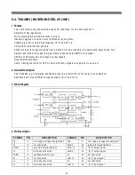
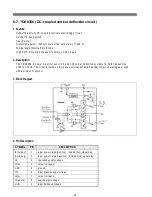
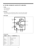
6-8. TDA7056 ( 3W MONO BTL AUDIO PUTPUT AMPLIFIER )
1. Feature
N o s w itc h -o n /o ff click s
G o o d o ve ra ll sta bility
S h o rt c ircu it p ro o f
2. Description
T h e T D A 7 0 5 6 is a m o n o o u tp u t a m p lifie r c o n ta in e d in a 9 p in m e diu m p o w e r p a c ka g e .
T h e d e vic e is d e sig n e d fo r b a tte ry fe d p o rtab le m o n o re c o rd e rs ,ra d io s a n d te le vis io n .
3. Block Diagram
4. Pin Description
S YM B O L
PIN
D ES C R IP T IO N
nc
1
nc
Vp
2
positive supply voltage
input(+)
3
input signal
signal G N D
4
signal ground
nc
5
nc
)
6
)
pow er G N D
7
pow er ground
output(-)
8
output(-)
nc
9
nc
Input
)
Output(-)
Signal
ground
Pow er
ground
n.c.
n.c.
2
3
5
4
7
1
9
8
6
n.c.
Positive
supply
Summary of Contents for MV1421
Page 1: ...SERVICE MANUAL MV1421 1422 4822 34cm 48cm Televideo Effective December 1999 MV4822SERV ...
Page 6: ...4 3 BLOCK DIAGRAM 3 1 Audio Signal Flow ...
Page 7: ...5 3 2 Video Signal Flow ...
Page 8: ...6 3 3 TV and monitor power switching ...
Page 22: ...20 3 Block Diagram ...
Page 53: ......
Page 54: ......
Page 55: ......
Page 117: ...2 Main PCB Assy Circuit Diagram SECTION BEFORE AFTER MAIN TUNER ...
Page 118: ...3 SECTION BEFORE AFTER SUB TUNER ...
Page 125: ...10 Exploded View MV1421 model ...
Page 126: ...11 Exploded View MV1422 model ...
Page 127: ...12 Exploded View MV4822 model ...
Page 128: ...13 Exploded View DVT 20F9 model ...
Page 129: ...14 Exploded View DVT 21F1 model ...
Page 130: ...15 Exploded View DVT 21F2 model ...


