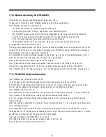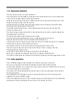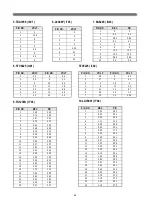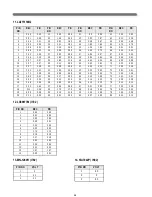
36
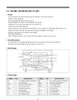
6-13. LC89977M ( CCD DELAY LINE IC )
1. Feature
B u ilt-in co m b filte r fu n ctio n fo r c olo ur n o ise re d u c tio n
B u ilt-in 1 H d e la y lin e fo r lu m in a n ce sig n a l
3 fsc (1 3 .3 M H z ) c lo c k is g e n e ra te d b y P L L c irc u it a n d is sy n ch ro n iz e d w ith fs c (4 .4 3 M H z) c lo c k in p u t.
C o m b filte r for ch ro m in a n c e n o is e re d u ctio n
A v a ila b le s y ste m : PA L ,G B I,4 .4 3 N T S C
T h e o u tp u t p h a se o f lu m in a n c e s ig n a l is th e s a m e ph a s e o f in p u t s ig n a l
P a ck a g e : M F P -1 4 S
2. Functions
2 C C D s hift re g iste rs. ( fo r c hro m in an c e s ig n a l, a n d fo r lu m ina n c e s ig n a l )
T im in g ge n e ra to r an d cloc k d riv e r fo r C C D .
D e la y tim e s e le c tiv e c ircu it.
S ig n a l a d d e r u n it o n C C D s h ift re g is te r.
A u to -b ia s c irc u it.
S yn c tip c la m p circ u it fo r lu m in a n c e s ig n a l.
C e n te r b ias circ u it fo r c h ro m in a n ce sig na l.
S a m p le an d h o ld c ircu it a n d o utp u t A m p .
3 fsc c lo c k g e n era to r w ith P L L c ircu it.
3 fsc c lo c k o u tp u t circ u it.
H ig h v o lta g e g e n e ra to r fo r C C D R e s e t D ra in (R D ).
3. Block Diagram
Summary of Contents for MV1421
Page 1: ...SERVICE MANUAL MV1421 1422 4822 34cm 48cm Televideo Effective December 1999 MV4822SERV ...
Page 6: ...4 3 BLOCK DIAGRAM 3 1 Audio Signal Flow ...
Page 7: ...5 3 2 Video Signal Flow ...
Page 8: ...6 3 3 TV and monitor power switching ...
Page 22: ...20 3 Block Diagram ...
Page 53: ......
Page 54: ......
Page 55: ......
Page 117: ...2 Main PCB Assy Circuit Diagram SECTION BEFORE AFTER MAIN TUNER ...
Page 118: ...3 SECTION BEFORE AFTER SUB TUNER ...
Page 125: ...10 Exploded View MV1421 model ...
Page 126: ...11 Exploded View MV1422 model ...
Page 127: ...12 Exploded View MV4822 model ...
Page 128: ...13 Exploded View DVT 20F9 model ...
Page 129: ...14 Exploded View DVT 21F1 model ...
Page 130: ...15 Exploded View DVT 21F2 model ...

