8
6
7
4
5
2
3
1
E
D
C
B
A
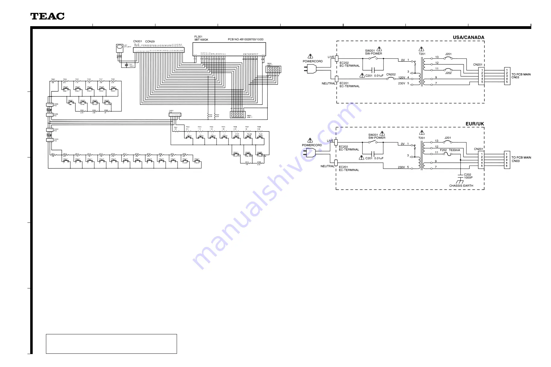
SCHEMATIC DIAGRAM
PD-D2750
DISPLAY PCB, 10KEY PCB, FUNCTION PCB, POWER PCB
Compact Disc Changer
P
PD
D--D
D22775
50
0
1 st Issue; October 2001
INSTRUCTIONS FOR SERVICE PERSONNEL
BEFORE RETURNING APPLIANCE TO THE CUSTOMER, MAKE LEAKAGE-
CURRENT OR RESISTANCE MEASUREMENTS TO DETERMINE THAT EXPOSED
PARTS ARE ACCEPTABLY INSULATED FROM THE SUPPLY CIRCUIT.
NOTES:
1. Resistor values are in ohms (k=kilo-ohms, M=megohms).
2. Capacitor values are in microfarads (p=picofarads).
3.
£
Parts marked with this sign are safety critical components.
They must always be replaced with identical components-refer
to the appropriate parts list and ensure exact replacement.
注 意
1. 抵抗の単位はΩ(k=kΩ,M=MΩ)です。
2. コンデンサの単位はμF(p=pF)です。
3.
£
マークのある部品は安全規格重要部品です。
交換するときは必ずティアック指定の部品を使用してください。
Summary of Contents for PD-D2750
Page 3: ...2 EXPLODED VIEWS AND PARTS LIST 3 EXPLODED VIEW 1...
Page 5: ...EXPLODED VIEW 2 5...
Page 8: ...3 PC BOARDS AND PARTS LIST 8 MAIN PCB...
Page 9: ...9...
Page 12: ...4 WIRING DIAGRAM 12...
Page 13: ...5 BLOCK DIAGRAM 13...
Page 14: ...6 IC BLOCK DIAGRAM 14 IC...
Page 15: ...15...
Page 16: ...16...


