4
SL-D910
3 ADJUSTMENTS AND CHECKS
3-1 TUNER SECTION
Use a screwdriver with a plastic or ceramic grip for all adjustment.
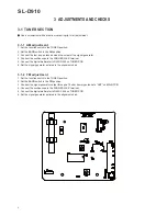
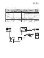
3-1-1 AM adjustment
1. Set the function switch to the TUNER position.
2. Set the BAND switch to the AM position.
3. Connect the test loop antenna across the output of the signal generator.
4. Connect the oscilloscope to the PHONES JACK terminal.
5. Connect the digital multimeter to R430/R453 on TUNER PCB.
6. Set the signal generator as listed in the alignment chart.
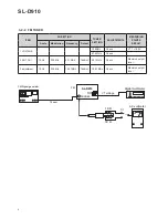
3-1-2 FM adjustment
1. Set the function switch to the TUNER position.
2. Set the BAND switch to the FM position.
3. Connect the signal generator output through a 75 ohm dummy antenna to "ANT" on MAIN PCB.
4. Connect the oscilloscope to the PHONES JACK terminal.
5. Connect the digital multimeter to R450/C404 on TUNER PCB.
6. Set the signal generator as listed in the alignment chart.
Summary of Contents for SL-D910
Page 3: ......
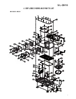
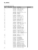
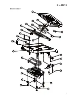
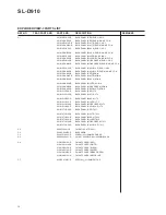
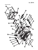
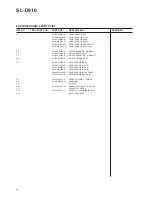
Page 7: ...7 SL D910 4 EXPLODED VIEWS AND PARTS LIST EXPLODE VIEW 1...
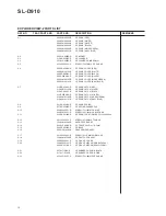
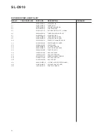
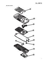
Page 9: ...9 SL D910 EXPLODE VIEW 2...
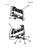
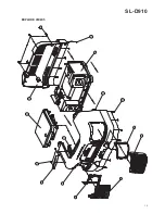
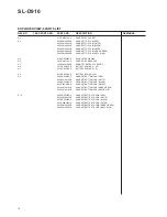
Page 11: ...11 SL D910 EXPLODE VIEW 3...
Page 13: ...13 SL D910 EXPLODE VIEW 4...
Page 15: ...15 SL D910 EXPLODE VIEW 5...
Page 17: ...17 SL D910 EXPLODE VIEW 6...
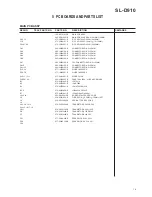
Page 20: ...SL D910 20 MAIN PCB...
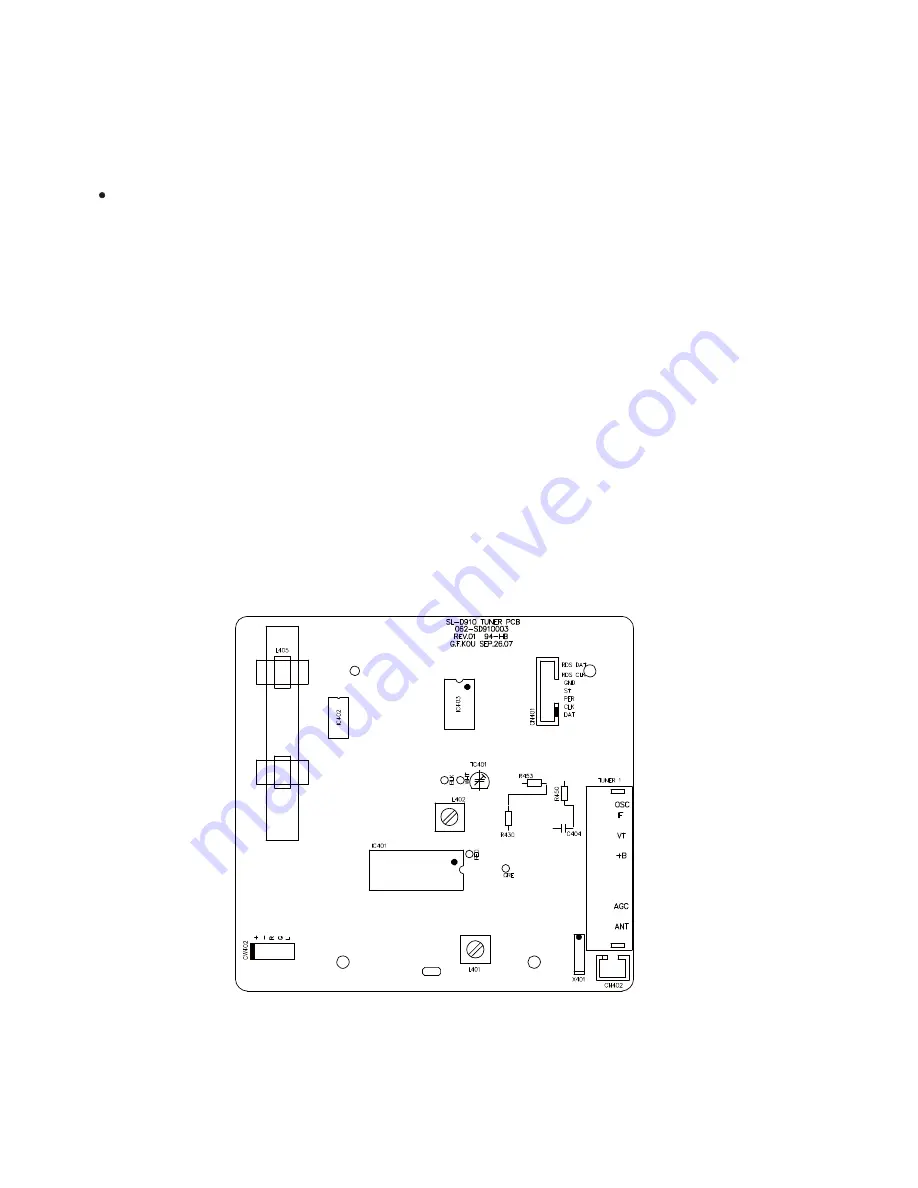
Page 22: ...22 SL D910 TUNER PCB...
Page 24: ...24 SL D910 CONTROL PCB CD PCB...
Page 26: ...26 SL D910 BASS VR PCB SNOOZE PCB PHONE JACK PCB CD SWITCH PCB AUX JACK PCB...
Page 28: ...28 SL D910 USB JACK PCB REMOTE CONTROL PCB...
Page 29: ...SL D910 29 6 WIRING DIAGRAM MAIN PCB...
Page 30: ...30 SL D910 CD PCB...
Page 32: ...SL D910...
Page 33: ...SL D910 AM FM STEREO DIGITAL RADIO WITH CD PLAYER MAIN PCB...
Page 34: ...CD PCB SL D910 AM FM STEREO DIGITAL RADIO WITH CD PLAYER...
Page 35: ...TUNER PCB SL D910 AM FM STEREO DIGITAL RADIO WITH CD PLAYER...


