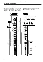
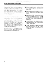
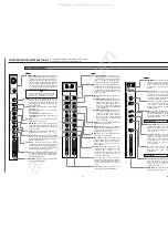
background image

13

Recorder Controls 

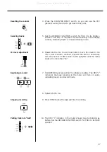
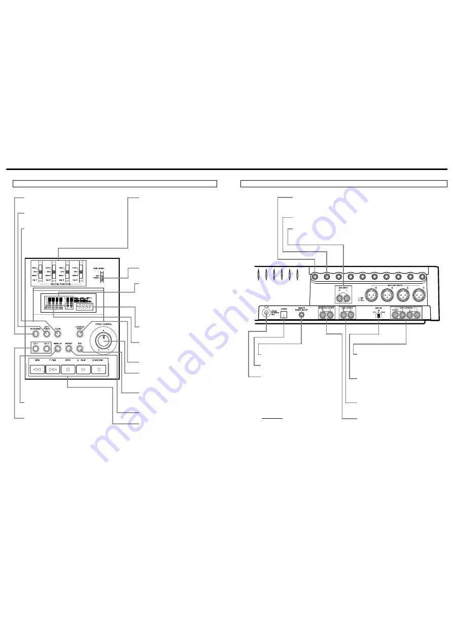
RECORD FUNCTION 1-4 : These control

which track(s) will be recorded when the
master RECORD and the PLAY key is
pressed, and choose where the signal to
be recorded is coming from.

œ

Setting to DIRECT routes the
channel signal directly to the tape
(channel 1 is recorded on track 1,
channel 2 on track 2, and so on).
Recording level is adjusted by the
channel fader only.

œ

When recording the stereo mix: As
the labels indicate, tracks 1 and 3
are recorded with the mix in BUSS
L, and tracks 2 and 4 are recorded
with the mix in BUSS R.

TAPE SPEED : HIGH is 3-3/4 ips (9.5 cm/sec.),

double the standard (NORMAL) cassette
tape speed of 1-7/8 ips (4.8 cm/sec.).

Meters : The meters numbered 1-4 show the

playback or the record level of the
respective tape tracks. The average
record level should be in the center (0),
but occasional peaks up to +6 scale are
acceptable.

The MONITOR meters show the level of
mixes selected by the MONITOR
switches.

Tape counter : A four-digit display that

shows the distance the tape has moved
from a zero reference point.

REC indicators : They blink to show the

corresponding tracks are in record
ready, and glow solid when recording
starts.

COUNTER RESET : Press to change the

counter to "0000".

PITCH CONTROL : Increases or decreases

the speed of the transport in play and
also in  Record, over a 12% range
(approx.).

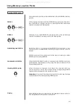
RTZ (Return To Zero) : Lets the tape fast

wind to the counter zero point. The tape
will automatically start playing from the
zero point if PLAY is pressed after RTZ.

REPEAT : Lets the tape play over and over

between two memo points.

Transport keys : Principally these work the

same as on any cassette recorder.

MEMO IN : Hold this key down and press LOC 1

or 2 to load the current counter location into
the MEMO 1 or 2 register.

LOC 1 and 2 : When used together with MEMO

IN, these keys let you load the current
counter location into memory. If only LOC 1
or 2 is hit, the tape will be located to the
MEMO 1 or 2 point. Pressing LOC for half a
second or more allows you to check the
memo point on the display.

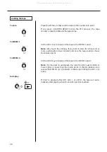
REHEARSAL : Lets you program a punch-in/out

sequence to be used for rehearsals and for
AUTO IN/OUT.

AUTO PUNCH : Executes the punch-in recording

actually on tape as you practiced in
REHEARSAL.

CLEAR : Disables the REHEARSAL and AUTO

IN/OUT functions.

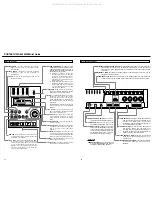
PORTASTUDIO 424 MKIII Brief Guide

14

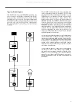
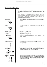
REMOTE PUNCH IN/OUT: Connect an

optional RC-30P footswitch to this jack.

POWER switch: Push in to turn on the 

424 MKIII, and push again to turn it off.

POWER connector: Connect the power

cable of the PS-424MKIII power supply
to this connector. Never use any power
supply with the 424 MKIII except the
PS-424MKIII power supply which is
appropriate for your area’s voltage.

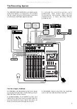
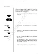
TAPE OUTPUTS: These jacks receive signals directly

from tape tracks 1–4 and are connected to the
inputs of an external mixer, or of another
multitrack recorder for making a backup copy of
your 4-track master, as required.

DBX NR switch: Normally, leave this switch in the

ON position. When you use track 4 for
recording and playing back MIDI sync tones or
timecode, set to SYNC, to set the dbx NR on for
tracks 1 through 3, and off for track 4.

LINE OUTPUT L and R: Normally, connect these

jacks to the left and right inputs of your
mixdown deck.

MONITOR OUTPUT L and R: These are connected to

an amplifier powering the control room
speakers.

EFFECT 2 SEND/TAPE CUE OUT: The signal available at this jack comes from either post

channel fader for connection to an additional effects device, or from the tape for
connection to a studio speaker system, as selected by means of the EFFECT 2/TAPE
CUE switch.

EFFECT 1 SEND: For sending post-fader signals to effects devices. The returns may be

plugged into the stereo inputs.

SUB INPUT L and R: Provide a direct route to the MASTER fader. You may connect an

outboard mixer here. The SUB IN R jack is also used to record sync tones on track 4.

Rear Panel Connections

On the front

PHONES (not shown) : This carries the same

mix as the MONITOR OUTPUT jacks, as
selected by the MONITOR switches.

All manuals and user guides at all-guides.com

Summary of Contents for Tascam Portastudio 424 MkIII

Page 1: ...OWNER S MANUAL 424 3D0023100A All manuals and user guides at all guides com a l l g u i d e s c o m...

Page 2: ...ion 41 Output section 41 424 MKIII Recorder Cassette loading and dbx system 42 Transport controls 43 Track controls 44 Displays 44 Autolocators 44 Optional Accessories 47 Care and Maintenance 48 49 Ho...

Page 3: ...ucture grounding of the lead in wire to an antenna discharge unit size of grounding conductors location of antenna discharge unit connection to grounding electrodes and requirements for the grounding...

Page 4: ...inadvertent connection to the mains supply If this product is not provided with a mains plug or one has to be fitted then follow the instructions given below IMPORTANT DO NOT make any connection to t...

Page 5: ...ack recorder Effects processors etc The Recording System The Three Steps to Multitrack In TRACKING and Overdubbing the mixer inputs are usually microphones or instruments going to different tracks of...

Page 6: ...ain Mix The illustration below shows how input signals pass through the 424 MKIII Mixer section After the MASTER fader they go to the L R LINE OUT Signal Flow in the 424 MKIII Mixer Understanding the...

Page 7: ...ockwise and the MONITOR LEVEL is turned up you can hear the tape playback in the headphones and MONITOR outputs You can adjust the monitor level of each track by adjusting its TAPE CUE control The cha...

Page 8: ...the mixer has a stereo output however using the DIRECT feature you can record on any or all of the 4 tracks at one time For more details see Recording on More Than Two Tracks Simultaneously page 22 T...

Page 9: ...n stereo cassette recorders Material recorded on the 424 MKIII must be mixed down to stereo for final distribution The 424 MKIII needs the entire width of the tape to record its four tracks eliminatin...

Page 10: ...a cassette length that is as close as possible to the length of the program you plan to record Cassettes C 60 length and shorter are often made from thicker stock than longer cassettes The tape used...

Page 11: ...m a point just after the channel fader TAPE CUE The EFFECT 2 controls can be switched to act as the TAPE CUE level controls by means of the correspondingly labeled switch and adjust the playback level...

Page 12: ...1 or 2 point Pressing LOC for half a second or more allows you to check the memo point on the display REHEARSAL Lets you program a punch in out sequence to be used for rehearsals and for AUTO IN OUT A...

Page 13: ...y The POWER switch is located on the back beside the power cable 4 Plug your headphones into the front PHONES jack so you can hear the input signal going to the mixer section of the 424 MKIII 5 Set th...

Page 14: ...our voice in the left side of the headphones When using a line level source such as electronic instruments instead of the mic the TRIM does not need to be turned up very far if at all 16 As a trial le...

Page 15: ...the mic You will see meter 1 move If no level or too low a level is shown continue to speak into the mic and slowly turn the channel 1 TRIM control to the right MIC until the meter peaks at no more th...

Page 16: ...de the MONITOR SELECT LINE OUT switch to the center MONO position 3 Press the RTZ key The tape will rewind automatically stopping at the zero counter point 4 Press PLAY 5 Turn the MONITOR LEVEL contro...

Page 17: ...Set the channel 1 INPUT selection switch to the left MIC LINE position 2 Turn the channel 1 PAN control all the way to the right R position 3 Bring the channel 1 fader to 7 4 Bring the MASTER fader t...

Page 18: ...d 11 Press STOP to stop recording 12 The REC 2 indicator in the meter should now be blinking as before Set TRK 2 RECORD FUNCTION switch back to its SAFE position and the indicator will turn off Begin...

Page 19: ...mixes will be recorded on Note that in this method the mixer channel number has nothing to do with what track the instrument winds up on Any mixer channel can be panned to any track These mixer channe...

Page 20: ...channel as well as with channel 5 or 6 the signal level will be doubled as it is being mixed through two channels together Use the stereo channels 7 and 8 to add additional signal sources to the mix...

Page 21: ...R fader to the shaded area between 7 and 8 3 Set the MONITOR SELECT LINE OUT switch to the L R position 4 Set all the INPUT select switches on the input channels to the right TAPE position 5 Press PLA...

Page 22: ...nto Record mode then press PLAY on the 424 MKIII 14 When recording is done stop both machines rewind the mixdown tape and listen to it If the mixdown tape does not sound right make the necessary corre...

Page 23: ...d down a new memory point is established and the previous memory point is erased MEMO points can t be entered while the tape is locating to either MEMO point or during REPEAT If the COUNTER RESET butt...

Page 24: ...for 0 5 second or more autolocation does not start and only the tape counter shows the location point Hit the LOC 2 key to fast wind the tape to the MEMO 2 point Note For the deck to autolocate the c...

Page 25: ...automatically rewind to the lower MEMO location and start over Press any transport keys except Play The function pressed will be activated If the tape is wound outside the repeat loop points the REPE...

Page 26: ...on channel 2 until the MONITOR level meters read a maximum of from 0 to 3 and adjust the MONITOR LEVEL control for the desired headphone listening level 5 Play the instrument You ll hear it together w...

Page 27: ...nch in The IN indicator will glow on the display and an LED will start flashing above the RECORD button The counter readout at which the key was pressed is stored as the PUNCH IN point 5 When the tape...

Page 28: ...During the punch in setting or the rehearsal process if you press the footswitch after STOP the tape will rewind to your START point Rehearsal function is not available while the 424 MKIII is in the...

Page 29: ...he memory points will be cleared and AUTO will turn off in the display The 424 MKIII lets you manually punch in too There are 2 ways to initiate the punch in recording The first is with the transport...

Page 30: ...blinking and locate the tape to a point a little before the error then press PLAY 3 When you reach JUST BEFORE the error press the footswitch This has the same effect as pressing RECORD and the REC 2...

Page 31: ...3 along with another live part onto track 4 for a total of four parts on one track Bouncing Tracks Ping Pong Ping pong procedure In this example we will combine material from tracks1 3 onto track 4 1...

Page 32: ...n on solid and track 4 will record a copy of what is on tracks 1 3 9 You ll hear the mix being recorded on track 4 in the headphones 10 Once the recording is done press STOP 11 The REC 4 indicator wil...

Page 33: ...eturns from the reverb unit In this method the stereo inputs function as effect returns Setting effect send levels Setting the output level of effect devices The goal is not to distort the device whil...

Page 34: ...nput channel There s no law that says the output of an effects device must be plugged into a STEREO INPUT either They can also be plugged into LINE INPUTS just like any other source if you are cautiou...

Page 35: ...are themselves a computer type digital language and cannot be recorded on analog tape it is necessary to convert them to recordable FSK Frequency Shift Keying signals using an appropriate converter su...

Page 36: ...atures and Controls 40 7 INPUT select switches channels 1 4 This is used to control what the source of the channel is The left position MIC LINE is used when recording microphones instruments in track...

Page 37: ...for MIDI virtual tracks you should probably set this switch to MON while recording tape tracks and L R on mixdown Stereo Input Section 18 MONITOR SELECT switches These switches determine what you will...

Page 38: ...NR system provides a net noise reduction broadband not just hiss of about 30 dB and also permits a net gain in tape headroom of about 10 dB allowing recordings over a 90 dB dynamic range Cassette Loa...

Page 39: ...tape at high speed in the forward direction 33 STOP key Stops any tape motion and disables all transport modes 34 PLAY key a Press this key alone to start playback b If pressed together with RECORD r...

Page 40: ...switch This provides a playback loop or block repeat between MEMO 1 and MEMO 2 points Track Controls 38 RECORD FUNCTION switches 1 4 These switches put the respective tracks into Record Ready Recordi...

Page 41: ...arting location Pressing RTZ 44 gets you back to that location 51 REHEARSAL switch Helps you rehearse a punch in without erasing anything until you are ready to actually record p 29 52 AUTO PUNCH swit...

Page 42: ...f any excess cleaning fluid with a dry swab Even though the heads used in your 424 MKIII have high wear resistance and are rigidly constructed performance degradation or electro mechanical failure can...

Page 43: ...g fluid onto the shaft Clean thoroughly and wipe off excess fluid Degaussing the Tape Path 1 Hold the degausser about 1 m 3 feet away from the recorder Turn it on slowly move in to the tape path Move...

Page 44: ...vel 60 dBV 1mV MIC position 20 dBV 0 1 V LINE position Maximum Input Level 3 dBV 1 4 V at Trim Min MIC LINE INPUT Ch 1 6 1 4 phone jack x 6 Input Impedance 5 6k ohms Nominal Input Level 50 dBV 3mV MIC...

Page 45: ...input level of 60 dBV 4 MIC INPUTS to LINE OUTPUT 60 dB at a nominal input level of 60 dBV 1 LINE INPUT to LINE OUTPUT 76 dB at a nominal input level of 10 dBV 4 LINE INPUTS to LINE OUTPUT 70 dB at a...

Page 46: ...ion 22 W In these specifications 0 dBV is referenced to 1 Volt Actual voltage levels are also given in parentheses 0 316 V for 10 dBV rounded off to 0 3 V dbx is a registered trademark of dbx Incorpor...

Page 47: ...54 53 Block Diagram All manuals and user guides at all guides com...

Page 48: ...ts WD1 8YA U K Phone 01923 819699 TEAC DEUTSCHLAND GmbH Bahnstrasse 12 65205 Wiesbaden Erbenheim Germany Phone 0611 71580 TEAC FRANCE S A 17 Rue Alexis de Tocqueville CE 005 92182 Antony Cedex France...

Reviews: