28
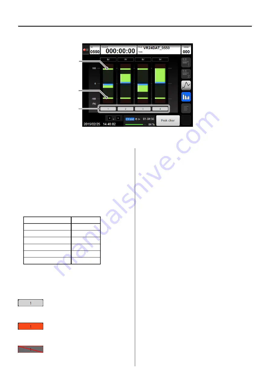
6-6-3. Analog data bar meter display
Peak
Peak
Channel numbers
6. Basic operation
Touch the bar meter display button to show bar meters
of the analog data on the display. Bar meters will not be
shown for channels that have their input settings OFF,
and their channel numbers will appear gray.
A small version of these bar meters appear at the bot-
tom right of the home screen and graphed waveform
display screens.
Bar meters
The bar meters are colored by level as follows.
Level (%)
Color
100 to 127
Red
10 to 100
Green
0 to 10
Blue
0 to −10
Blue
−10 to −100
Green
−100 to −127
Red
Channel numbers
The colors of the channel numbers depend on their
analog input status as follows.
o
These are examples of CH1.
Usual
The analog data level is greater than -100% and less
than 100%.
Over range
The analog data level is greater than 100% or less
than -100%.
ICP sensor interruption detection
An ICP sensor is being used and an interruption is
detected
Channels shown
Bar meters can be shown for a maximum of four chan-
nels at the same time, and it is not possible to designate
which channels are shown.
Peak indicators
Peak indicators begin to be shown when the unit
becomes record ready and when recording starts.
o
Peak indicators are reset whenever recording starts
from a record ready state.
o
When recording stops, the bar meters disappear, but
the peak indicators remain.
o
Touch the Peak clear button to clear peak indicators.
Peak clear button
This resets the peak indicators.
Summary of Contents for VR-24
Page 1: ...Analog Visual Recorder Owner s Manual Z VR 24 D01255010D...
Page 67: ...67 15 Exterior drawings 260 77 12 5 186 Unit mm...
Page 70: ...70...
Page 71: ...71...


