48
Unit substitution
Use to apply a coefficient to the measured voltage to
convert the physical quantity. The physical quantity is
calculated using the following formula.
Unit substitution
= (measured voltage − offset) × coefficient
Actual load cal.
Calibrate by applying an actual load to the sensor.
See “7-5-2. Actual load calibration” on page 33 for
the operation procedures.
Apply to all channels
Touch this button to apply the settings shown to all
channels.
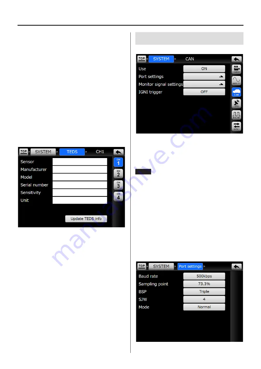
10-2-3. TEDS
This screen shows the TEDS data read when the unit is
turned on.
Each item will be shown for channels that have had
TEDS data read.
o
Use the buttons on the right side of the screen to
select the channel to show.
Update TEDS info
Touch this button to load TEDS sensor data again.
o
Touch this button to refresh TEDS data when, for
example, a TEDS sensor was connected after the
unit was already on.
10-3. CAN
When Use is ON, the setting items are shown.
IGNI trigger
When ON, it will function as a start trigger.
o
When using CAN, there are limits on the sampling fre-
quency and number of recording channels.
NOTE
When the sampling frequency is set to 96 kHz or
102.4 kHz, set the Analog settings “Record channel
count” and CAN, GPS and pulse channels so that the
total number of channels does not exceed 4.
Enabling these inputs will use the following number of
channels.
CAN: 2 channels
GPS: 1 channel
Pulse: 1 channel
10-3-1. Port settings
10. SYSTEM settings
Summary of Contents for VR-24
Page 1: ...Analog Visual Recorder Owner s Manual Z VR 24 D01255010D...
Page 67: ...67 15 Exterior drawings 260 77 12 5 186 Unit mm...
Page 70: ...70...
Page 71: ...71...


