background image

50

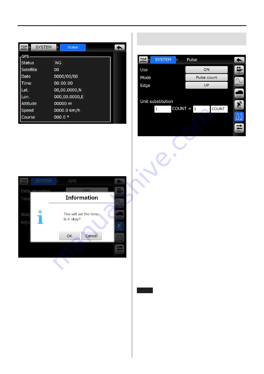
10-4-2. Status (reception status)

If the reception status is “NG”, GPS is not connected or 
no signal is being received from a satellite.
If the reception status is “OK”, the GPS data being 
received will be shown.

10-4-3. Adjust time

Use to set the unit's clock according to the GPS time 
information.


o

To set the time without using GPS, input it using the 
“Date time” item on the MISC settings screen.

10. SYSTEM settings

10-5. Pulse

When Use is ON, the setting items are shown.

Use

Set the function of the PULSE/TRIG IN connector.
OFF:  Use as an external trigger input connector.
ON:

Use as a pulse input connector.


o

When using pulse input, there are limits on the 
sampling frequency and number of recording 
channels.

Mode

Pulse count

The pulse count is recorded.

rpm

The number of revolutions per minute is recorded.

Edge

This sets the timing for counting pulses.

Pulses per revolution


o

This is shown when the mode is rpm.

Unit substitution

Use to apply a coefficient to the measured count to 
convert the physical quantity.


o

This is shown when the mode is pulse count.

NOTE

When the sampling frequency is set to 96 kHz or 
102.4  kHz, set the Analog settings “Record channel 
count” and CAN, GPS and pulse channels so that the 
total number of channels does not exceed 4. 

Enabling these inputs will use the following number of 
channels.
CAN: 2 channels
GPS: 1 channel
Pulse: 1 channel

Summary of Contents for VR-24

Page 1: ...Analog Visual Recorder Owner s Manual Z VR 24 D01255010D...

Page 2: ...output 19 DC power supply output 19 Connector on unit 19 Pin assignments 20 6 Basic operation 21 6 1 Handling recording media 21 6 1 1 CFast cards 21 6 1 2 Handling 21 6 1 3 CFast card insertion and...

Page 3: ...10 4 3 Adjust time 50 10 5 Pulse 50 10 6 Sync 51 10 6 1 VR sync 51 10 6 2 WX sync 52 10 6 3 LX sync 52 11 FILE settings 53 11 1 RecFile recording settings 53 11 2 PlayFile playback settings 53 11 2 1...

Page 4: ...their occurrence because of the use of these products 1 Introduction 1 2 Included accessories If anything is missing or damaged contact us For contact information see the last page AC adapter 1 AC pow...

Page 5: ...input are supported as standard o o CFast cards enable high capacity data recording at high transfer rates Recorded data is easy to use and multiple cards can be prepared allowing easy creation of sep...

Page 6: ...le and ASCII format header file each time recording stops or pauses Data file Contains data converted from analog to digital etc binary format with a dat file extension Header file Contains recording...

Page 7: ...channel to the second sampling channel and so on until the last sampling channel This order is called the INTERLACED format and the format name is recorded in STORAGE_ MODE in the header file The stru...

Page 8: ...GER SLOPE 8 000000e 005 8 000000e 005 8 000000e 005 8 000000e 005 X_OFFSET 1 0 Y_OFFSET 0 000000e 000 0 000000e 000 0 000000e 000 0 000000e 000 NUM_SAMPS 2928000 DATA DEVICE VR 24 CH1 VR 24_CH1 RANGE...

Page 9: ..._SAMPS Number of data items recorded per channel DATA The data that follows this entry is specific to this unit and it might differ from the for mats of other models DEVICE VR 24 CH1_ The channel name...

Page 10: ...ULSE_CH Pulse data channel recorded CAN_CH CAN data channel recorded GPS_CH GPS data channel recorded VR 24_VERSION VR 24 APP and AD versions and serial number o o In synchronized recording the VR 24...

Page 11: ...pe D CLARATION DE CONFORMIT Nous TEAC AUDIO EUROPE Liegnitzer Stra e 6 82194 Gr benzell Allemagne d clarons sous notre propre respon sabilit que le produit TEAC d crit dans ce mode d emploi est confor...

Page 12: ...hat has a CSA mark on the plug 3 2 Connecting cameras The circular connector of a dedicated camera cable sends control signals and supplies power for one camera When connected to the main unit the LAN...

Page 13: ...3 Connections c Measurement microphone To ANALOG IN Pulse input Earphone Microphone Camera Piezoelectric accelerometer Example Voltage output type with built in preamp 724ZT triaxial ICP that supports...

Page 14: ...arched for during playback Play 7FWD button Press when the system is stopped or playback ready to start playback Press when the unit is record ready to start recording Pause 9PAUSE button Press when t...

Page 15: ...ep the recording media slot cover closed when not loading or unloading recording media Do not open the recording media slot cover when the system is operating K EARPHONE jack Connect the included earp...

Page 16: ...signed for this product can also be connected here These two functions can be used separately Q LX recording synchronization connector LX SYNC Use this to synchronize recording with a data recorder fr...

Page 17: ...nt S S Cooling ports These are ventilation holes to cool the unit Do not block these holes 4 Names and functions of parts 4 5 Rear T T Cooling fan This is an exhaust fan to cool the unit Do not block...

Page 18: ...IN connector Function Use to input pulse signals or external trigger signals o o When using as a pulse input connector refer to 10 5 Pulse on page 50 o o When using as an external trigger input conne...

Page 19: ...ION Do not connect anything to the unused pins 5 4 GPS remote control signal input connector GPS REMOTE Function Use to connect an optional GPS receiver sold sepa rately to control recording with cont...

Page 20: ...ed 9 Ground GND 10 STOP status 11 REC status 12 FWD status 13 PAUSE status 14 Ground GND 15 PPS input for GPS 16 STOP input 17 REC input 18 FWD input 19 PAUSE input 20 Ground GND CAUTION o o Do not co...

Page 21: ...trouble inserting the CFast card confirm the notch location and that it is oriented correctly o o Read the CFast card operation manual o o Always remove the CFast card before transportation 6 1 3 CFa...

Page 22: ...into standby before inserting or removing an SDHC card Never remove an SDHC card when the unit is in use including when recording or playing back Removing a card could cause recording to fail or recor...

Page 23: ...it on Confirm that the included AC adapter or the DC power cable sold separately is connected and turn the STANDBY ON switch on When the Home Screen appears on the display the sys tem is ready for use...

Page 24: ...diagram The status of the system can be changed in the following manner 0REC 7FWD 9PAUSE 7FWD 9PAUSE 8STOP 7FWD F FWD mREW 9PAUSE 8STOP 8STOP Stopped Select playback file Stop playback Turn power on...

Page 25: ...e file d Recording file information FILE name of file being recorded The appearance changes according to the status of the unit When playing back or ready for playback this shows the name of the file...

Page 26: ...ving not shown when standing by Pulse OFF ON ON and receiving pulse not shown when standing by Synchronization OFF waiting for synchronization VR sync master waiting for synchronization VR sync slave...

Page 27: ...ite balance button When record ready or recording readjusts the white balance Exposure adjustment buttons Usually the brightness will be adjusted so that it is optimal but you can touch the button to...

Page 28: ...their analog input status as follows o o These are examples of CH1 Usual The analog data level is greater than 100 and less than 100 Over range The analog data level is greater than 100 or less than...

Page 29: ...igger settings display Start trigger Stop trigger The start and stop trigger settings are shown by icons No trigger External trigger Level trigger Recording time Timeout Triggers set modes If multiple...

Page 30: ...able recording time is 1 day 4 hours and 56 minutes The available recording time shown is an estimate o o CFast cards cannot be used when unformatted for example immediately after purchase Format them...

Page 31: ...ettings on page 58 for details about settings ATTENTION When using triggers and intervals to start recording automatically put the unit into a record ready state The unit will not detect triggers if j...

Page 32: ...cording Start recording When the number of repetitions is set to 2 or more recording will start at the set time and stop after the set recording time has elapsed Then the system will become record rea...

Page 33: ...button on the top panel and then touch the SYSTEM w Analog w Channel settings buttons in order 3 Set the sensor for actual load calibration and touch the Actual load cal button 4 Select the actual lo...

Page 34: ...e physical quantity conversion value if it has not been set o o When the TEDS sensor is changed or the Update TEDS info button is touched the physical quantity conversion value will be reset 7 6 Start...

Page 35: ...ch button when the system is playing back to skip to the beginning of the current file and make it playback ready Press the mREW search button when the system is playback ready to skip to the beginnin...

Page 36: ...tton to open that settings screen b TOP button Return to the TOP menu c Settings screen name This shows the current settings category d Setting value selection buttons Touch a button to show the optio...

Page 37: ...be shown but they cannot be changed 2 Touch the button for the type of setting that you want to change When you touch a setting button a screen where you can change multiple related settings will ope...

Page 38: ...showing the set value A list of setting options will appear For example press the 48kHz sampling frequency button to open the following screen 2 Touch a button to set that value The list of setting op...

Page 39: ...other than the charac ters are as follows BS Delete the character to the left of the cursor OK Confirm the input characters Cancel Cancel the input gt Move the cursor in the direction of the arrow SH...

Page 40: ...ion Sync Synchronization type Connection check FILE RecFile Recording device File name Comment PlayFile File search Media Format TRIGGER Mode OFF Trigger Start conditions Level trigger External trigge...

Page 41: ...ries 96kHz series 102 4kHz series Sampling frequency 48kHz 96kHz 48kHz 24kHz 12kHz 6kHz 3kHz 1 5kHz 240Hz 102 4kHz 51 2kHz 25 6kHz 12 8kHz 5 12kHz 2 56kHz 1 28kHz 256Hz Bit depth 24bit 24bit 16bit Rec...

Page 42: ...Intel Intel Motorola Value type Unsigned Unsigned Signed Float Double Name Signal XX 20 ASCII characters maximum Unit 20 ASCII characters maximum Coefficient 1 0000000 Offset 0 0000000 IGNI trigger OF...

Page 43: ...layFile Parameter Default value Setting values Note File search 9 8 9 FILE Media Parameter Default value Setting values Note Format 9 8 10 TRIGGER Mode Trigger Parameter Default value Setting values N...

Page 44: ...MISC Date time Parameter Default value Setting values Note Set date and time Display Year month day Year month day Month day year Day month year 9 8 14 MISC Parameters Parameter Default value Setting...

Page 45: ...auto matically Tungsten 3100K Use this setting when in an area lit by light bulbs Fluorescent 4200K Use this setting when in an area lit by fluorescent lights Daylight 5000K Use this setting when outd...

Page 46: ...ERA 1 10 2 Analog Sampling series Sets the sampling frequency series Sampling frequency This shows the set sampling frequency Bit depth Sets the analog digital resolution quantization bit depth Record...

Page 47: ...el settings Make input amplification settings for each channel o o Use the buttons on the right side of the screen to select the channel to set Range Sets the input amplification range Set the range t...

Page 48: ...buttons on the right side of the screen to select the channel to show Update TEDS info Touch this button to load TEDS sensor data again o o Touch this button to refresh TEDS data when for example a TE...

Page 49: ...uency is set to 96 kHz or 102 4 kHz set the Analog settings Record channel count and CAN GPS and pulse channels so that the total number of channels does not exceed 4 Enabling these inputs will use th...

Page 50: ...se input connector o o When using pulse input there are limits on the sampling frequency and number of recording channels Mode Pulse count The pulse count is recorded rpm The number of revolutions per...

Page 51: ...sible when set to synchronize Set synchronization to OFF in order to play back recordings 10 6 1 VR sync Preparation 1 Use a synchronization cable to connect the VR 24 WX SYNC connectors of the master...

Page 52: ...vent marks can only be set on the WX 7000 10 SYSTEM settings 10 6 3 LX sync Preparation 1 Use a synchronization cable to connect the AQ VU connector of the LX 110 120 to the VR 24 WX SYNC connector of...

Page 53: ...omment Sets the recording file comment o o See 9 4 Inputting characters as setting values on page 39 for how to input characters 11 2 PlayFile playback settings 11 2 1 File search This shows a list of...

Page 54: ...TTENTION Format media with this unit before using them with the unit Formatting media 1 Touch the Format button A confirmation screen will open when you touch the Format button 2 Touch the OK button t...

Page 55: ...Pre trigger recording will not occur if set to OFF Stop conditions Icons are shown on the button for the triggers that are ON External trigger Level trigger Recording time Timeout Post trigger Post tr...

Page 56: ...rements will be judged ful filled when any set condition is met Count Measurement starts when the set count logic is fulfilled CH1 CH2 CH3 CH4 Touch the icon for a channel to turn use ON OFF for it Ed...

Page 57: ...met Count Measurement stops when the set count logic is fulfilled CH1 CH2 CH3 CH4 Touch the icon for a channel to turn use ON OFF for it Edge UP The trigger requirement will be judged to be fulfilled...

Page 58: ...58 12 1 2 Interval See 7 4 2 Interval recording on page 32 for details about each setting 12 TRIGGER settings...

Page 59: ...n When the back light is off the touchscreen and the unit buttons function as backlight activation buttons For exam ple pressing the play 7FWD button when the backlight is off will turn the backlight...

Page 60: ...Sampling display Sets the sampling notation Frequency Each item is shown by sampling frequency Band Each item is shown by sampling frequency band o o If the Sampling series is set to 96kHz series the...

Page 61: ...e system beeps when warnings occur 13 4 2 Calibration 13 4 2 1 Amp calibration o o Before beginning measurements we recommend letting the system warm up for at least 10 minutes and then calibrating am...

Page 62: ...12 2 3 1 25 2 56 1 1 50 0 625 1 28 0 5 0 240 0 100 0 256 0 1 o o Band Series 1 sampling frequency 2 4 Series 2 sampling frequency 2 56 Recording time The times given in the table below are based on us...

Page 63: ...trigger input connector BNC connector CAMERA 2 camera input connectors Control signal connector 6P circular connector Video signal connector LAN connector ANALOG IN 4 analog input connectors BNC conn...

Page 64: ...each channel and anti aliasing filter Input frequency flatness characteristics within 0 5 dB Offset drift within 0 1 1V input range Calibration function Offset calibration function included Phase cont...

Page 65: ...1 ppr 24 bit depth 1 30000 rpm when 1 ppr Measurement precision Pulse count mode Within 2 rpm mode 2 or less o o Analog signal and pulse input data sampling are not synchronized o o If pulse input cea...

Page 66: ...rrent 6 5 A Output power 104 W External dimensions W H D 68 35 153 mm Weight 650 g or less Operating conditions Operating temperature humidity range 0 to 40 C 10 to 80 no condensation Storage temperat...

Page 67: ...67 15 Exterior drawings 260 77 12 5 186 Unit mm...

Page 68: ...24 unit Are you using media that has been confirmed to work with the VR 24 CFast card not recognized If a CFast card is not recognized after removing and inserting it turn the VR 24 off and then on a...

Page 69: ...CLAIMED IN NO EVENT SHALL THE COPYRIGHT OWNER OR CONTRIBUTORS BE HELD LIABLE FOR ANY DIRECT INDIRECT INCIDENTAL SPECIAL EXEMPLARY OR CONSEQUENTIAL DAMAGES INCLUDING BUT NOT LIMITED TO PROCUREMENT OF S...

Page 70: ...70...

Page 71: ...71...

Page 72: ...ia 90640 U S A Phone 1 323 726 0303 TEAC EUROPE GmbH Bahnstrasse 12 65205 Wiesbaden Erbenheim Germany Phone 49 611 7158 0 TEAC SALES TRADING Room 817 Block A Hailrun Complex 6021 Shennan Blvd Phone 86...

Reviews: