56
13. SYSTEM menu
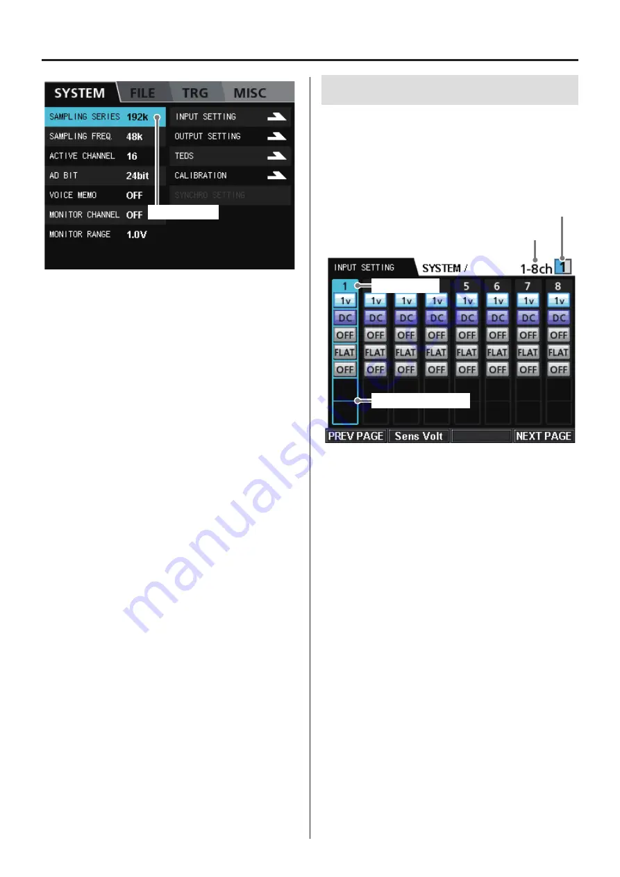
Current selection
For details about the sampling frequency, analog-digital conver-
sion bit depth (AD BIT) and number of recording channels (ACTIVE
CHANNEL) Parameters, see “Sampling frequencies and bands” on
page 77 and “Number of channels that can be recorded simulta-
neously” on page 77.
Selection
Use the VALUE knob and the up, down, left and right (
5
,
b
,
g
,
t
) buttons to change the selection.
Press the VALUE knob to change the setting of the selected parameter.
SAMPLING SERIES
Sets the sampling frequency series.
The four series options are 192 kHz, 200 kHz, 204.8 kHz and 131.0 kHz.
SAMPLING FREQ.
Sets the sampling frequency.
The 8 available sampling frequency options correspond to the cur-
rent sampling series.
AD BIT
Sets the analog-digital conversion bit depth (quantization bits).
The options are 16-bit and 24-bit.
ACTIVE CHANNEL
Sets the number of recording channels.
The options are the possible number of recording channels for the
current system.
VOICE MEMO
Turn voice memo recording ON or OFF.
Voice memos are not recorded during the pre-trigger interval.
Moreover, the beginnings of voice memos and the beginnings of
data are aligned when played back, so the timing might be different
from when recorded.
MONITOR CHANNEL
Sets the channel monitored.
The options are the channels available in the current system and OFF.
Set this to OFF when you do not want to monitor the output.
MONITOR RANGE
Sets the monitoring output range.
The setting range is from 1.0 V to 5.0 V in 0.1 V increments.
13-1. INPUT SETTING
From the SYSTEM menu, select the INPUT SETTING item and press
the VALUE knob to open the INPUT SETTING screen.
The first channel numbers are shown with their settings beneath
them.
Change the channel numbers shown with the F1 (PREV PAGE) and
F4 (NEXT PAGE) buttons.
Channels shown
Expansion unit shown
Current selection
Current channel settings
Channels shown
This shows the range of channels currently shown.
Expansion unit shown
This shows the number of the expansion unit that has the channels
currently shown.
Selection
Use the VALUE knob and the left and right (
g
,
t
) buttons to
change the selection.
If you move further right from the selection at the right edge of the
screen, the next page will open. In the same manner, moving left
from the left edge will open the previous page.
Press the VALUE knob to change the setting of the selected parameter.
PREV PAGE (F1 button)
Opens the previous page.
Sens Volt (F2 button)
Opens the sensor voltage menu screen.
NEXT PAGE (F4 button)
Opens the next page.
Summary of Contents for WX-7000
Page 1: ...WIDE BAND DATA RECORDER Owner s Manual Z WX 7000 D01190210J ...
Page 84: ...84 19 Exterior drawings WX 7016 340 348 10 8 220 13 8 123 82 40 15 WX 7032 164 82 40 40 15 ...
Page 85: ...85 WX 7064 246 82 40 40 40 40 15 WX 7096 360 370 396 19 Exterior drawings ...


