22
29
D 14
A2
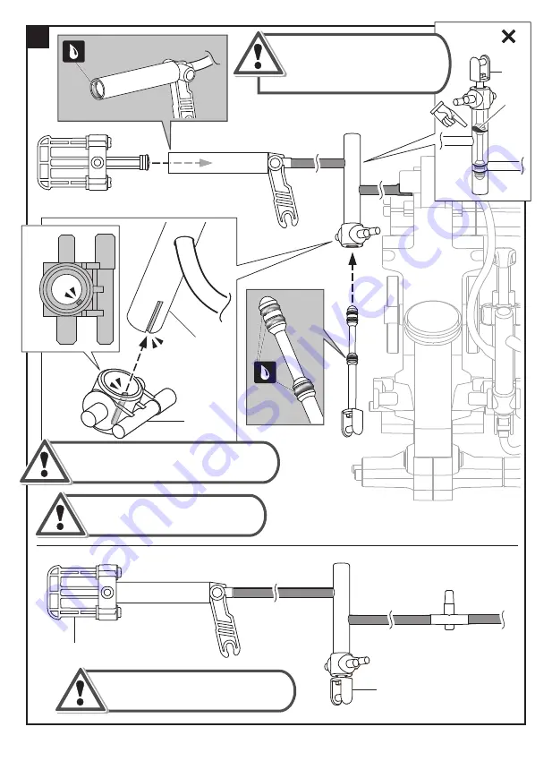
Pu sh & p u ll oiled p arts B10 and B13
se veral tim es to m ake su re they
m ove sm oothly.
B13
B10
D 14
D o n o t m i x u p D 9 & D 14, m a k e
s u r e t o u s e D 14 f o r a s s e m b l y .
N o t e :
M ake su re to lock A2 into D 14 f irm ly.
Take of f B13 if P10 ( R ed C ap )
was twis ted du ring as s em bly.
U ntwis t P10 and re- ins ert
B13 into A2.
B13
P10
I ncorrect
Summary of Contents for AIR SCREAMER
Page 1: ...Discovery From the Makers of TTG 631 10 ASSEMBLY INSTRUCTION MANUAL ...
Page 21: ...P1x4 C1 19 4 5 2 Scale 1 1 1 ...
Page 23: ...D13 21 10 D13 9 Gently tap D13 with hammer to the bottom as shown below Incorrect ...
Page 28: ...26 17 4 2 3 1 1 Route the air tube to the position as shown above Correct Incorrect ...
Page 29: ...Make sure the airtube is facing the correct direction 27 18 19 P1x4 2 4 3 Scale 1 1 1 5 1 ...
Page 30: ...D17 1 28 20 21 1 1 2 2 Scale 1 1 P1 B4 ...
Page 32: ...30 23 24 Correct Incorrect ...
Page 33: ...1 31 25 4 3 2 1 ...
Page 34: ...D6 C4 32 26 27 2 3 2 4 5 1 1 6 1 P19 P19 02 02 ...
Page 35: ...Scale 1 1 P1x5 33 28 29 Top View Correct Incorrect ...
Page 36: ...34 30 1 3 4 2 Ensu re the correct direction of air tu be C orrect I ncorrect ...
Page 37: ...D19 D18x2 35 B6 P18 1 2 2 31 32 D10 1 ...
Page 40: ...2 38 B9 P18x5 37 39 38 Make sure there is no oil on connector for assembly ...
Page 41: ...B5 B5 39 B12 P18x5 P7 40 41 Correct Incorrect Correct Incorrect ...
Page 42: ...1cm B11 40 P18x5 42 43 ...
Page 43: ...4 1 F i n i sh ed P 19 P 19 06 07 44 ...
Page 50: ...48 Notes ...
Page 51: ...49 Notes ...


