background image

contact

TeachLogic, Inc. 


Customer Service Dept.
1688 Ord Way
Oceanside, CA 92056
     

1

800

588

0018

sales@teachlogic.com
1

760

631

1283

www.teachlogic.com

five year limited warranty

TeachLogic IR products are guaranteed to be free 
of defects in workmanship or material for a period 
of five (5) years from date of original purchase, 
subject to the following conditions:
1. Warranty excludes defects caused by normal  
    use and wear, any abuse, or failure to use the   
    product in accordance per instructions.
2. Warranty is void if damage occurred because 
    of misuse, or attempted repair or modification 
    by unauthorized personnel.
3. Warranty on batteries is for two (2) years. 
4. Warranty does not extend to finish.
5. All warranty service will be provided by  
    TeachLogic or authorized service center
6. Warranty is made to the original purchaser and 
    may not be transferred to another user.
7. Warranty service rendered will be on a repair 
    or replacement basis, whichever TeachLogic 
    deems to be most prudent for customer  
    satisfaction and economic feasibility.  

TeachLogic will only accept warranty shipments 
accompanied by Return Authorization Number 
previously assigned by TeachLogic personnel. 
Advance warranty replacements will be made per 
the discretion of TeachLogic personnel. 

TeachLogic will pay return shipping cost on all 
warranty repairs or replacements.

8

owner’s manual

20

Maxim III

Summary of Contents for Maxim III

Page 1: ...owner s manual Infrared Wireless Microphone System...

Page 2: ...owner s manual Maxim III...

Page 3: ...notes Date of Purchase Model Number Serial Number Notes...

Page 4: ...rs of reliable performance We appreciate your confidence by your selection of our product It is TeachLogic s intent to uphold that confidence by providing factory assistance and dealer support We hope...

Page 5: ...kinking or abrasion Object Protection Locate the operating unit so it will not be subjected to falling objects or water entry Internal Service User should not attempt to service this product All inte...

Page 6: ...ger BRC 55 Ceiling Sensor ICS 55 Installation of Ceiling Sensor Installation of Ceiling Speakers Installation of Wall Mount Speakers System Wiring Page Pass Through Fire Alarm RS 232 Features Security...

Page 7: ...ight beams to the sensor located in the corner of the room Now when you talk into the microphone the microphone element modulates the light beam causing it to flicker in sync with your speech The sens...

Page 8: ...0 connectivity throughout the classroom regardless of body position or orientation The system is comprised of an infrared detecting sensor s installed in the ceiling The sensor collects the IR wireles...

Page 9: ...he Maxim III system is comprised of a microphone transmitter either the Sapphire IRT 60 or Handheld IRH 35 for voice transmission to a ceiling sensor ICS 55 that sends the signal to the receiver ampli...

Page 10: ...put is achieved by the unidirectional Cardioid microphone and a unique free air suspension system With a built in breath filter the Sapphire can function as a pass around hand mic The strategic alignm...

Page 11: ...ng diodes Diodes at top and bottom of handle for increased Coverage 2 Top aimed out 6 Bottom 360 2 Bottom aimed down 360 IR radiation for as sured connectivity Two AA Duracell re chargeable NiMH batte...

Page 12: ...at needs to be installed on the ceiling It comes with a mounting support bracket and 50 feet of plenum rated cable with RCA connector on each end The ideal location for the dome sensor would be in the...

Page 13: ...is in the center of the ceiling This will provide a clear signal path for the IR transmission from the transmitter to the dome sensor without obstruction In addition you will have 360 coverage and wi...

Page 14: ...dge in place above the hole Pull speaker cable back down through speaker hole With a pointed tool or paper clip lift up and remove speaker grille Set speaker on top of ladder and connect speaker cable...

Page 15: ...eaker Observe speaker polarity Connect wire with printed writing to terminal and wire unprinted textured to the terminal Route speaker cable to the receiver amplifier in a safe least visible tidy mann...

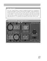
Page 16: ...ECURITY ALERT FIRE ALARM AC DC 5 24V 1KHZ 300 100 MIC 1 Tx 2 Gnd 3 Rx COM N O N C COMP ANTI HUM 4ohm load 25watts amp 10KHZ 3KHZ ON OFF AUX SENSITIVITY ALS PAGE INPUT OUTPUT 100V 70V 25V _ _ Assistive...

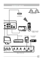
Page 17: ...UTER DVD SENSOR POWER 19V DC 3 4A MAX R COMP ANTI HUM ON OFF 5 VOLT OUTPUT Lesson Capture Recorder DVD Player MP3 Player Computer Ceiling Sensor Drop in Charger Infrared Transmitter Sapphire IRT 60 Ce...

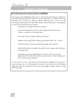
Page 18: ...to the 2 pin Phoenix connector of the Page input Reconnect the 2 pin green Phoenix connector Determine the signal level of the paging system 25v 70v or 100v Set the slide switch to the appropriate spe...

Page 19: ...e of the TeachLogic amplifier When interfaced to the fire alarm relay contact output all audio devices microphones dvd etc will turn SILENT In the event of a fire this will help to lower the overall d...

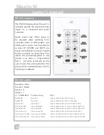
Page 20: ...3a 55 50 Gain Computer DOWN Gain Computer DOWN 4c 69 6e 6b 78 3a 47 61 69 6e 3a 44 56 44 3a 44 4f 57 4e Gain Computer MUTE Gain Computer MUTE 4c 69 6e 6b 78 3a 47 61 69 6e 3a 44 56 44 3a 4d 55 54 45...

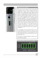
Page 21: ...the side for initiating the Security Alert Simply holding down the button for 4 seconds closes a contact closure on the rear panel of the TeachLogic amplifier and sends the Security Alert signal to th...

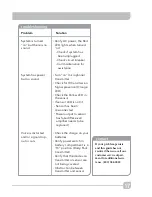
Page 22: ...itch transmitter on Observe power LED Blue use fully charged battery only Observe signal presence LED Orange on receiver adjacent to Mic volume control Stand under or in front of a speaker Slowly adju...

Page 23: ...ck the Yellow LED in the sensor If sensor LED is not lit Sensor has been disconnected Power output to sensor has failed Receiver amplifier needs to be replaced Check the charge on your batteries Verif...

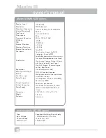
Page 24: ...Two Amplifiers 50 watts total RMS 25 watts ea RMS 4ohm min per channel One Phoenix Connector ch A B 19VDC 3 4A 65W CE CSA UL Listed 8 1 2 W x 1 3 4 H x 7 1 2 D 2 lb 2oz Aluminum Receiver Input Modula...

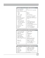
Page 25: ...ry being charged Battery fully charged 5 VDC 1 Amp 7 3 4 L x 2 3 4 W x 3 3 4 H 1 lb 12 oz Sapphire transmitter IRT 60 specs Six 1 600 Ft 60 Ft Line of Sight Full Medium Low Very Low Battery Lithium io...

Page 26: ...n by unauthorized personnel 3 Warranty on batteries is for two 2 years 4 Warranty does not extend to finish 5 All warranty service will be provided by TeachLogic or authorized service center 6 Warrant...

Page 27: ......

Page 28: ...2 1688 Ord Way Oceanside CA 92056 1 800 588 0018 sales teachlogic com 1 760 631 1283 www teachlogic com 5 28 14...

Reviews: