background image

EN

6

44$5353"7$8%4)035$0634&536$,t*/4536$5*0/."/6"-

EN

RUN TIME

The largest factor in run time is the capacity of the battery pack. A larger mAh rating  
increases the amount of run time experienced. 
The condition of a battery pack is also an important factor in both run time and speed.  
The battery connectors may become hot during driving. Batteries will lose performance  
and capacity over time.
Driving the vehicle from a stop to full speed repeatedly will damage the batteries  
and electronics over time. Sudden acceleration will also lead to shorter run times.

TO IMPROVE RUN TIMES

t

Keep your vehicle clean and well maintained.

t

Allow more airflow to the ESC and motor.

t

Change the gearing to a lower ratio. A lower ratio decreases the operating temperature  
of the electronics. Use a smaller pinion gear or larger spur gear to lower the gear ratio.

t

Use a battery pack with a higher mAh rating.

t

Use the optimum charger to charge battery packs (Visit your local hobby dealer for  
more information).

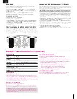
PERFORMING A CONTROL DIRECTION TEST

Perform a control test with the vehicle wheels off the ground. If the wheels rotate after the 
vehicle is powered ON, adjust the TH Trim knob until they stop. To make the wheels move 
forward, pull the trigger. To reverse them, wait for the wheels to stop, then push the trigger. 
When moving forward, the wheels should maintain a straight line without any steering wheel 
input. If not, adjust the ST Trim knob, so the wheels maintain a straight line without having to 
turn the steering wheel.

CHANGING THE TRAVEL ADJUST SETTINGS

Set the travel adjust settings with all four vehicle wheels off the ground. The throttle end point 
and brake end point adjustments will cause the wheels to spin at full speed. Have an assistant 
safely hold the vehicle securely while adjusting these settings.

CAUTION:

 Keep hands, hair and all loose clothing away from any moving parts, espe-

cially the wheels, while setting the travel adjust end points. Serious injury may result.

1. Hold the trigger in the full brake position and turn the steering wheel to Full Right while pow-

ering on the transmitter. The LED flashes rapidly, indicating the programming mode is active.

2. Throttle End Point: Continue holding full throttle. Turn the TH TRIM knob to adjust the full 

throttle end point.

3. Brake End Point: Hold the trigger in the full brake position. Turn the TH TRIM knob to adjust 

the full brake end point. Return the trigger to the center position.

4. Left Steering End Point: Hold the steering wheel in the full left position. Turn the ST TRIM 

knob to adjust the left end point.

5. Right Steering End Point: Hold the steering wheel in the full right position. Turn the ST TRIM 

knob to adjust the right end point. Return the steering wheel to the center position.

6. Power off the transmitter to save the travel adjust settings. 

The minimum Travel is 75%, and the Maximum travel is 150%.

IMPORTANT:

 If the travel is changed on the DX2E, you must rebind and calibrate the SRS6000.

SPECIFICATIONS

Type

Sensorless

Constant/Peak

60A/90A

Resistance

0.0004 Ohm

Function

Forward/Brake–Forward/Brake Reverse

Operation

Proportional forward, proportional reverse with braking delay

Input Voltage

2-3S LiPo, 6-8 Cell NiMH

BEC Output

6V/2A

Overload Protection

Thermal

Dimensions (LxWxH)

40mm x 32mm x 19mm

Weight

51 g

ESC LED STATUS

t

In the neutral position, no LEDs are lit.

t

The red LED lights when the car is moving forward, reversing or braking (sensorless motor).

t

The green LED lights when the car is moving forward, reversing or braking (sensored motor).

t

The red LED flashes if the battery voltage has reached LVC.

t

The red and green LEDs light alternately, indicating the ESC overheating protection is enabled.

t

The red LED lights if the receiver signal is incorrect or missing.

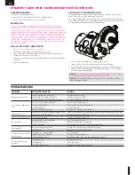
MOTOR TO ESC CONNECTION

Motor wires can be connected to the ESC in any order. 

Tip:

 If the motor turns in the wrong direction, reverse the connection of the 2 outside motor 

wires. The center wire must remain in the center and cannot be moved to another motor tab.

NOTICE: 

Always disconnect the battery from the ESC when you have finished operating 

your vehicle. The ESC’s switch only controls power to the receiver and servos. The ESC will 
continue to draw current when connected to the battery, resulting in possible damage to 
the battery through over discharge.

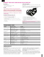
ESC CALIBRATION PROCEDURE

Ensure proper ESC function by calibrating the ESC to your transmitter inputs.
1. Power OFF the ESC. 
2. Ensure your transmitter is powered ON, the throttle is not reversed, the throttle trim is neutral 

and the throttle travel range is at 100%. Disable any special functions such as ABS, etc.

3. Press the SET button while powering ON the ESC. Release the button as soon as the red 

LED starts to flash and the motor emits a beep. 

4. Calibrate the throttle points by pressing the SET button once after each step. 

 - Neutral (1 green flash; 1 beep)—leave the throttle at rest, untouched
 - Full throttle (2 green flashes; 2 beeps)—pull the throttle fully back
 - Full brake/reverse (3 flashes; 3 beeps)—push the throttle fully forward

5. Power off the ESC. The ESC is calibrated and ready to run.

ESC FUNCTIONS AND MODES

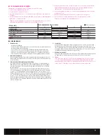
The ESC includes programming options so you can adjust the way your vehicle performs.  
Refer to the included settings table to adjust the ESC for your driving conditions.

DYNAMITE

®

 TAZER™ 60A BRUSHLESS ESC (DYNS2405)

Summary of Contents for 22S Maxxis

Page 1: ...y removed place the vehicle upside down and pull full throttle for a few short bursts until the water has been removed CAUTION Always keep hands ngers tools and any loose or hanging objects away from...

Page 2: ...rsonal transponder or lights If AVC is disabled see DISABLING THE STABILITY ASSIST FUNCTION all 6 channels including the Aux channels can operate as servo channels SPEKTRUM DX2E ACTIVE RADIO SYSTEM 1...

Page 3: ...ight You would use maximum sensitivity during high speed driving or drag racing when you want the vehicle to stay in a straight line Turn the ST RATE knob counter clockwise to reduce the sensitivity T...

Page 4: ...d point 5 Right Steering End Point Hold the steering wheel in the full right position Turn the ST TRIM knob to adjust the right end point Return the steering wheel to the center position 6 Power off t...

Page 5: ...force A higher value provides stronger braking but can also cause the wheels to lock resulting in loss of control of the car 6 Punch Select from start mode Level 1 Soft to Level 9 Very aggressive If...

Page 6: ...ears stripped Replace transmission gears Drive pin broken Check and replace drive pin Steering does not work Servo plug not in receiver properly Make sure the steering servo plug is connected to the r...

Page 7: ...urchaser or user are not prepared to accept the liability associated with the use of the Product purchaser is advised to return the Product immediately in new and unused condition to the place of purc...

Page 8: ...lich es in einer Art und Weise zu benutzen die eine eigene Gef hrdung und die anderer oder Besch digung an anderem Eigentum ausschlie t Das Modell ist ferngesteuert und anf llig f r bestimmte u ere Ei...

Page 9: ...ben ein paar Mal kurz Vollgas bis das Wasser aus dem Reifen entfernt ist ACHTUNG Entfernen Sie Wasser in den Reifen durch Gas geben Nehmen Sie die Karosserie ab drehen das Fahrzeug auf den Kopf und ge...

Page 10: ...eaktivieren der Stabilit ts Assistenzfunktion nach SPEKTRUM DX2E RADIO SYSTEM 1 Sicherstellen dass der Geschwindigkeitsregler ausgeschaltet ist 2 DieVerriegelung derAkku Abdeckung drehen so dass der a...

Page 11: ...der bei Drag Racing wenn das Fahrzug auf einer geraden Linie bleiben sollten So verringert sich bei erh hen des Gainwerts der m gliche Lenkausschlag Drehen Sie den ST Rate Drehknopf gegen den Uhrzeige...

Page 12: ...d in der voll links Position Drehen Sie den ST TRIM Knopf um die Gr e des linken Lenkausschlages zu justieren 5 Endpunkt Lenkung rechts Halten Sie das Lenkrad in der voll rechts Position Drehen Sie de...

Page 13: ...werden Im Gegensatz zu den vorgegebenden Werten beziehen sich die programmierbaren Werte auf die Gesamtspannung und nicht die einzelne Zellenspannung 4 Start Mode Setzt den initialen Gaspunkt bei der...

Page 14: ...g for 3S batteries When using 2S batteries changing the pinion gear to a 23T 48P pinion will optimize speed power and ef ciency Installing a pinion gear with fewer teeth or a spur gear with more teeth...

Page 15: ...usma es f hren Dieses Produkt ist nicht f r den Gebrauch durch Kinder ohne die Aufsicht eines Erziehungsberechtigten vorgesehen Die Anleitung enth lt Sicherheitshinweise und Vorschriften sowie Hinweis...

Page 16: ...terf rences peuvent provoquer une perte momentan e de contr le Il est donc conseill de garder une bonne distance de s curit tout autour de votre mod le ce qui aidera viter les collisions ou les blessu...

Page 17: ...S HUMIDES t Evacuez l eau collect e par les pneus en les faisant tourner haute vitesse Retirez la carrosserie retournez le v hicule et donnez des courts coups d acc l rateur plein gaz jusqu ce que l e...

Page 18: ...sactiv Voir la section DESACTIVATION DE LA FONCTION DE STABILISATION pour d sactiver l AVC les voies auxiliaires pourront commander des servos METTEUR SPEKTRUM DX2E ACTIVE 1 Assurez vous que le contr...

Page 19: ...s d acc l ration en ligne droite Plus la sensibilit est lev e plus le d battement de la direction est faible Faites tourner le potentiom tre ST RATE dans le sens anti horaire pour r duire la sensibili...

Page 20: ...l arr t pleine vitesse de fa on r p t e nira par endommager la batterie et l lectronique Les acc l rations brutales r duisent l autonomie POUR AM LIORER L AUTONOMIE t Ayez toujours un v hicule entret...

Page 21: ...in jusqu l arr t complet du v hicule rel chez le frein puis freinez de nouveau le v hicule va reculer Quand vous reculez ou que vous freinez si vous appliquez de l acc l rateur la marche avant passe i...

Page 22: ...ed with optimal gearing for 3S batteries When using 2S batteries changing the pinion gear to a 23T 48P pinion will optimize speed power and ef ciency Installing a pinion gear with fewer teeth or a spu...

Page 23: ...produit Il est absolument indispensable de lire et de comprendre ces indications avant la premi re mise en service C est uniquement ainsi qu il sera possible d viter une manipulation erron e et des a...

Page 24: ...ossa causare danni al modello o ad altre propriet Questo modello controllato da un segnale radio potenzialmente soggetto a interferenze da molte fonti che non potete controllare Queste interferenze po...

Page 25: ...gliere la carrozzeria e rovesciare il veicolo poi dare alcune brevi accelerate nch l acqua non viene rimossa ATTENZIONE Durante l operazione precedente tenere sempre lontano dalle parti rotanti mani d...

Page 26: ...andare dei servi aggiuntivi SISTEMA RADIO SPEKTRUM DX2E ACTIVE 1 Accertarsi che l ESC sia spento 2 Ruotare il fermo del vano batteria per allineare la sezione piatta con il bordo del vano batteria 3 A...

Page 27: ...la sensibilit massima quando si va ad alta velocit e si vuole che il veicolo vada diritto Man mano che la sensibilit aumenta la corsa dello sterzo diminuisce Girare in senso antiorario la manopola ST...

Page 28: ...endo il volantino tutto a sinistra girare la manopola ST TRIM per regolare il ne corsa dello sterzo a sinistra 5 Fine corsa sterzo a destra Mantenendo il volantino tutto a destra girare la manopola ST...

Page 29: ...o regolare dei valori di soglia personalizzati A differenza dei valori preselezionati i valori personalizzati valgono per la tensione totale della batteria non per le celle singole 4 Modalit di accele...

Page 30: ...quelli della corona 3 Avvicinare gli ingranaggi e stringere le viti del motore 4 Togliere la carta Controllare il gioco in 3 5 punti differenti sulla corona muovendo leggermente gli ingranaggi AVVISO...

Page 31: ...ostante Questo prodotto non concepito per essere usato dai bambini senza una diretta supervisione di un adulto Il manuale del prodotto contiene le istruzioni di sicurezza di funzionamento e di manuten...

Page 32: ...Set molle LOS233021 Spring Cups and Clip Set LOS233022 Shock Seal Set LOS233023 Shock Caps 2 LOS233024 Shock Ends LOS234024 Suspension Arm Set LOS234025 Front Caster Block Set LOS234026 Hub and Spind...

Page 33: ...x 5 mm Ringschneide 10 Vis STHC M2 5 x 5mm CUV 10 Grani M2 5 x 5 mm con punta a coppa 10 TLR6288 Set Screws M3 x 2 5mm 10 TLR6313 Locknut M3 x 5 x 5 5mm 10 Einstellmutter M3 x 5 x 5 5 mm 10 crou auto...

Reviews: