EN
10
DBXL-E 2.0 RTR, AVC: 1:5 4WD DESERT BUGGY • INSTRUCTION MANUAL
PRECAUTIONS
• Never touch moving parts.
• Never disassemble while the batteries are installed.
• Always let parts cool before touching.
GEARING
Installing a pinion gear with fewer teeth or a spur gear with more teeth will provide greater
torque but will reduce top speed. Likewise, a pinion gear with more teeth or a spur gear with
fewer teeth will reduce torque and increase top speed. Care should be taken when installing
larger pinion gears as this can "overgear" the vehicle, resulting in overheating of the motor
and ESC. When testing different gearing options, pay close attention to the temperature
of the motor and speed control to ensure you are operating within the temperature range
of the components. The motor or ESC should never be so hot that it cannot be touched. If
temperatures are too hot, a different gearing combination with a lower pinion gear and/or
higher spur gear is suggested.
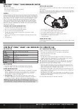
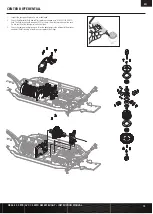
CHANGING THE PINION GEAR/GEAR RATIO
1. Remove the screw holding the pinion gear cover in place.
2. Loosen the set screw and remove the installed pinion gear.
3. Loosen the motor screws and slide the motor back.
4. Place the new pinion on the end of the motor shaft so the set screw is located
over the fl at on the shaft.
5. Position it so the teeth line up with the spur gear and secure the pinion by tightening
the set screw.
6. Set the gear mesh.
SPEKTRUM
™
FIRMA
™
780KV BRUSHLESS MOTOR
SETTING THE GEAR MESH
The gear mesh has already been set at the factory. Setting it is only necessary when changing
motors or gears.
Proper gear mesh (how gear teeth meet) is important to the performance of the vehicle. When
the gear mesh is too loose, the gears could be damaged. If the mesh is too tight, speed could
be limited and the motor and ESC will overheat.
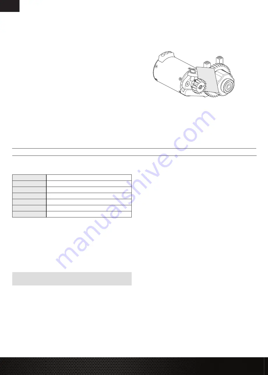
1. Loosen the motor screws and slide the motor back.
2. Put a small piece of paper between the pinion and spur gears.
3. Push the gears together while tightening the motor screws.
4. Remove the paper. Check the mesh at 3–5 different locations around
the spur gear for a small amount of movement.
5. Install the gear cover.
TELEMETRY SETTINGS
If using the Spektrum SMART Telemetry, set the motor pole count to 4 and the rollout distance
to 1.92" (49mm).
SPECIFICATIONS
Type
Sensorless, SMART Throttle Compatible
Output
160A
Function
Forward/Brake–Forward/Brake Reverse
Input Voltage
3-8S LiPo
BEC Output
6V/8.4V@5A
Dimensions (LxWxH)
70mm x 77mm x 44mm
Weight
280 g
ESC LED STATUS
• No ESC LEDs will glow when there is no throttle input from the transmitter.
• The red ESC LED glows when there is any throttle input from the transmitter.
AUDIBLE WARNING TONES
1. Input
Voltage:
The ESC checks the in put voltage when it is powered ON. If a voltage
problem is detected, the ESC continuously sounds 2 beeps with a 1 second pause
(xx-xx-xx). Power OFF the ESC and ensure the connections are secure and that
the battery power is not too low for safe operation.
2. Radio Connection:
The ESC checks radio signal input when it is powered ON.
If a problem is detected, the ESC continuously sounds 1 beep with a 2 second pause
(x--x--x). Power OFF the ESC and ensure the radio system is operating correctly.
NOTICE:
Always disconnect the battery from the ESC after operating your vehicle. The ESC’s
switch only controls power to the receiver and servos. The ESC will continue to draw current when
connected to the battery, resulting in possible damage to the battery through over discharge.
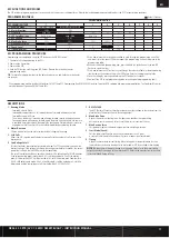
ESC CALIBRATION PROCEDURE
Complete the transmitter/receiver binding procedure prior to calibrating the ESC.
1. Set the transmitter throttle channel to 100% travel and center the throttle trim.
2. Connect a battery to the ESC battery lead.
3. Power on the transmitter.
4. Press and hold the SET button while turning on the ESC. Release the SET button when
the
red
LED begins to fl ash, indicating the ESC is in calibration mode. The ESC will enter
programming mode if the button is held for more than three seconds.
TIP:
The red LED should be fl ashing when the ESC enters calibration mode. If the green LED
is fl ashing the ESC has entered programming mode. Power off the ESC and repeat step 4,
releasing the SET button when the red LED begins to fl ash.
5. With the transmitter throttle trigger at the neutral position, press and release the ESC SET
button. The red LED will stop fl ashing, the green LED will fl ash one time and the motor will
make a tone to indicate the neutral position has been accepted.
6. While holding the throttle trigger at the full throttle position, press and release the ESC SET
button. The green LED will fl ash twice and the motor will make two tones to indicate the full
throttle position has been accepted.
7. While holding the throttle trigger at the full brake position, press and release the SET button.
The green LED will fl ash three times and the motor will make three tones to indicate the full
brake position has been accepted.
The motor will operate normally after calibration is completed.
SPEKTRUM
™
FIRMA
™
SMART 160A BRUSHLESS ESC (SPMXSE1160)


