background image

5

EN

DBXL-E 2.0 RTR, AVC: 1:5 4WD DESERT BUGGY • INSTRUCTION MANUAL

2.

1.

DRIVING PRECAUTIONS 

•  Maintain sight of the vehicle at all times.
•  Routinely inspect the vehicle for loose wheel hardware. 
•  Routinely inspect the steering assembly for any loose hardware. Driving the vehicle off-road 

can cause fasteners to loosen over time.

•  Do not drive the vehicle in tall grass. Doing so can damage the vehicle or electronics.

CAUTION:

 Do not discharge a Li-Po battery below 3V per cell. Batteries discharged 

to a voltage lower than the lowest approved voltage may become damaged, 

resulting in loss of performance and potential fi re when batteries are charged.

•  Do not apply forward or reverse throttle if the vehicle is stuck. 

Applying throttle in this instance can damage the motor or ESC.

•  After driving the vehicle, allow the electronics to cool before driving the vehicle again.

IMPORTANT:

 Keep wires away from all moving parts.

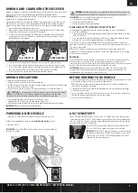
POWERING ON THE VEHICLE

1. Center the ST TRIM and TH TRIM dials on the transmitter and turn it on.

Install a fully charged battery pack per the 

Installing the Battery

 section.

2. Power on the ESC. 

IMPORTANT:

 The vehicle MUST remain on a fl at, level surface and motionless

for at least 5 seconds.

AVC

®

 SENSITIVITY

The ST RATE dial on the DX2e adjusts the sensitivity, or stability, value in the receiver. If you 
increase the sensitivity, the AVC

®

 system becomes more sensitive to the vehicle drifting left or 

right. You would use maximum sensitivity during high speed driving or drag racing, when you 
want the vehicle to stay in a straight line.

Turn the ST RATE knob counter-clockwise to reduce the sensitivity. 

Turn the ST RATE knob clockwise to increase the sensitivity.

IMPORTANT:

 The ST RATE knob will only adjust the sensitivity when 

the transmitter is bound to a DSMR

®

 receiver. When the transmitter 

is bound to a DSM

®

, DSM2

®

 or DSM Marine receiver, the ST RATE 

knob controls the steering dual rate.

BEFORE RUNNING YOUR VEHICLE

1. Check for free suspension movement. All suspension arms and steering components should 

move freely. Any binds will cause the vehicle to handle poorly. 

TIP:

 To increase the ride height and ground clearance of your vehicle, screw down the 

shock collars to compress the springs.

2. Charge a battery pack. Always charge the battery pack as per the battery and/or charger 

manufacturers’ instructions.

3. Set the transmitter steering trim. Follow the instructions to set the steering trim/subtrim so 

that the vehicle drives straight with no input to the steering.

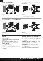
4. Perform a Control Direction Test.

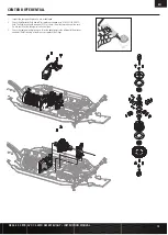
FULL THROTTLE

BRAKE/REVERSE

BINDING AND CALIBRATING THE RECEIVER 

Binding is the process of linking the SR6100AT receiver to your Spektrum transmitter. The AVC 
features on the receiver can be enabled or disabled during the binding process.

IMPORTANT:

 You must calibrate the SR6100AT receiver each time it is placed in bind mode, 

regardless of AVC being enabled or disabled.
Upon initial setup after the fi rst bind, the model must be confi gured for servo direction, trim 
and travel. Then the receiver must be rebound and calibrated to those settings for proper 
operation. Center the steering trim and throttle trim on the transmitter before beginning.
1.  Press and hold the bind button on the receiver.
2.  Power on the receiver. The orange LED fl ashes, indicating the receiver is in bind mode. 

Release the bind button after the orange LED illuminates.

3.  Put your transmitter in bind mode. The bind process is complete when the orange LED 

on the receiver remains lit. The receiver is now bound to the transmitter but must be 
calibrated before it will operate.

4.  Pull the transmitter trigger to full throttle, pause, then return the trigger to center.

5.  Push the transmitter trigger to full brake, pause, then return the trigger to center.
6.  Turn the transmitter steering wheel to full right, pause, then return the wheel to center.
7.  Turn the transmitter steering wheel to full left, pause, then return the steering wheel to 

center. The orange LED fl ashes to confi rm the settings have been accepted.

8.  Turn off the vehicle to complete the binding and calibration process.

CAUTION: 

When the bind process is complete, the throttle and steering channels are 

active. Keep hands and loose objects away from all spinning parts on the vehicle.

IMPORTANT:

 You must rebind the transmitter and receiver if you:

• Change the servo reversing after binding
• Change the travel after binding
• Change the receiver mounting orientation

DISABLING AVC

®

 TECHNOLOGY STABILITY ASSIST

If you participate in organized racing, you may be required to turn AVC technology off.
To turn off AVC technology:
1.  Connect power to the receiver and quickly press and release the bind button three times 

(within 1.5 seconds). 

2.  Press and hold the bind button and to put the receiver in bind mode. release the buton 

when the LED starts to fl ash rapidly, indicating it is in bind mode. 

When the AVC system has been disabled, the LED on the receiver will show three fl ashes 
upon power up, and then remain lit. The receiver is bound and operating normally when the 
LED remains illuminated.

TIP:

 If the AVC feature in the receiver is active and the AVC menu in the transmitter is 

Inhibited, AVC functions will default to the AUX 1 and AUX 2 operation, and in this scenario, 
AVC will not work correctly.

FAILSAFE

In the unlikely event that the radio link is lost during use, the receiver will drive the throttle 
channel to the neutral position. If the receiver is powered on prior to turning on the 
transmitter, the receiver will enter the failsafe mode, driving the throttle channel to the neutral 
position. When the transmitter is turned on, normal control is resumed.

IMPORTANT:

 Failsafe activates only in the event that signal is lost from the transmitter. 

Failsafe will NOT activate in the event that receiver battery power decreases below the 
recommended minimums or power to the receiver is lost.

Summary of Contents for Desert Buggy XL-E 2.0

Page 1: ...ng this vehicle please read all printed materials thoroughly Horizon Hobby is not responsible for inadvertent errors in this manual INSTRUCTION MANUAL BEDIENUNGSANLEITUNG MANUEL D UTILISATION MANUALE...

Page 2: ...s outside your control This interference can cause momentary loss of control so it is advisable to always keep a safe distance in all directions around your model as this margin will help avoid collis...

Page 3: ...mpressor or a can of compressed air to dry the vehicle and help remove any water that may have gotten into small crevices or corners Spray the bearings drive train fasteners and other metal parts with...

Page 4: ...VC TECHNOLOGY STABILITY ASSIST FUNCTION all 6 channels including the Aux channels can operate as servo channels SPEKTRUM DX2E ACTIVE RADIO SYSTEM AUX 1 Port AUX 2 Port AUX 3 Port AUX 4 Port Battery Pr...

Page 5: ...me it is placed in bind mode regardless of AVC being enabled or disabled Upon initial setup after the rst bind the model must be con gured for servo direction trim and travel Then the receiver must be...

Page 6: ...r The LED ashes rapidly indicating the programming mode is active 2 Throttle End Point Continue holding full throttle Turn the TH TRIM knob to adjust the full throttle end point 3 Brake End Point Hold...

Page 7: ...Camber Links Characteristics Lowering the Link Front Increases off power steering and makes the vehicle more responsive Handling consistency may decrease as off power steering increases Rear Increase...

Page 8: ...Shock Oil Characteristics Lighter Responds quicker and creates more chassis roll Use lighter oil as it gets colder Heavier Reacts slower and creates less chassis roll Use heavier oil as it gets warme...

Page 9: ...s off power traction with smoother steering entering the turn but has more on power steering Rear Increases stability in turns and on power steering Differential Light Weight Oil Heavier Weight Oil Fr...

Page 10: ...4V 5A Dimensions LxWxH 70mm x 77mm x 44mm Weight 280 g ESC LED STATUS No ESC LEDs will glow when there is no throttle input from the transmitter The red ESC LED glows when there is any throttle input...

Page 11: ...initial acceleration 9 Timing Adjusts the motor drive current timing More timing gives more performance but can lower ef ciency and cause damage to the motor and or ESC by overload or overheating NOT...

Page 12: ...ch to hold the shock body and remove the top cap Empty the uid from out of the shock 3 Hold the shaft with a multi wrench and remove the shock end Push the shaft into the shock body and remove through...

Page 13: ...hock cap spring and spring cup 1 Remove the front clip 2 Remove the cover and differential 3 Check the differential uid and re ll or replace as needed with DYN2656 30 000CS uid The uid level should be...

Page 14: ...eeded with DYN2656 30 000CS uid The uid level should be about 0 12 in 3 0mm from the top surface of the case Do not over ll or the differential unit might leak 4 Check the ring and pinion as well as t...

Page 15: ...ll or replace as needed with DYN2657 50 000CS uid The uid level should be about 0 12 in 3 0mm from the top surface of the case Do not over ll or the differential unit might leak 3 Check the spur gear...

Page 16: ...ation or maintenance iii modi cation of or to any part of the Product iv attempted service by anyone other than a Horizon Hobby authorized service center v Product not purchased from an authorized Hor...

Page 17: ...household waste disposal service or where you purchased the product Law These terms are governed by Illinois law without regard to con ict of law principals This warranty gives you speci c legal righ...

Page 18: ...4 x 22mm LOS255003 M5 x 20mm LOS255003 M5 x 14mm LOS255003 M5 x 32mm LOS255003 M5 x 40mm LOS255003 M4 x 4mm LOS255000 M5 x 5mm LOS255000 M6 x 5mm LOS255000 M6 x 12mm LOS255000 3 x 8mm LOS255002 M4 x 1...

Page 19: ...NUAL 8 x 19 x 6mm LOS257000 10 x 22 x 6mm LOS257001 12 x 24 x 6mm LOSB5972 7 x 10 x 4mm LOS257002 8 x 22 x 0 2mm LOS256001 13 x 16 x 0 3mm LOS256001 10 1 x 14 x 25mm LOS256001 M4 LOS256000 M5 LOS25600...

Page 20: ...e 13 T 1 5 M 8 mm Pignone 13T 1 5 m albero 8 mm LOS252066 Diff Housing Set Al 1 DBXL E Diffentialgeh use Satz Al 1 DBXL E Ensemble de bo tier de diff rentiel Al 1 DBXL E Set scatola differenziale allu...

Page 21: ...etooth facultatif DX2E Modulo Bluetooth opzionale DX2E SPMS906 Spektrum S906 1 5th Scale Servo Spektrum S906 1 5 Ma stab Servo Servo l chelle 1 5 Spektrum S906 Servocomando Spektrum S906 1 5 SPMSR6100...

Page 22: ...OS354003 Rear Hub Set Aluminum DBXL Nabensatz hinten Aluminium DBXL Ensemble de moyeu arri re aluminium DBXL Supporto mozzo posteriore alluminio DBXL LOSA99172 Camber Guage Sturzlehre Jauge de cambrur...

Page 23: ...S257001 LOS231057 LOS251011 LOS251011 LOS251011 LOS254065 LOS251102 LOS255002 LOS255002 LOS254030 LOS254009 LOS254009 LOS255002 LOS254063 LOS252125 LOS254006 LOS231057 LOS251096 LOS251094 LOS251092 LO...

Page 24: ...E PARTI LOS2521100 LOS251090 LOS255003 LOS255003 LOS251103 LOS251090 LOS251090 LOS251099 LOS251099 LOS251098 LOS251048 LOS251098 LOS255003 LOS251103 SPMXSE1160 LOS251090 LOS251099 SPMSR6100AT TLR25600...

Page 25: ...OS251046 LOS251045 LOS254064 LOS251100 LOS251102 LOS251053 LOS254065 LOS254006 LOS254005 LOS254065 LOS252113 LOS251102 LOS252116 LOS252020 LOSB3972 LOS252113 LOS251102 LOS254029 LOS254010 LOS254009 LO...

Page 26: ...DES PI CES VISTA ESPLOSA DELLE PARTI LOS45018 LOS45017 LOS45032 LOS45033 LOS45032 LOS45033 LOS250043 LOS250044 LOS250018 LOS250043 LOS250044 LOS250018 LOS250043 LOS250044 LOS250018 LOS250043 LOS25004...

Page 27: ...te Other Wet Dusty Blue Groove Dry Hard Packed Loose Loamy Smooth Rough Tight Open Indoor Outdoor Track Conditions Front Suspension Differentials Setup Sheet Stock Rear Suspension Radio Servo ESC Moto...

Page 28: ...Wet Dusty Blue Groove Dry Hard Packed Loose Loamy Smooth Rough Tight Open Indoor Outdoor Track Conditions Front Suspension Differentials Setup Sheet Rear Suspension Radio Servo ESC Motor Pinion Spur B...

Page 29: ...her Wet Dusty Blue Groove Dry Hard Packed Loose Loamy Smooth Rough Tight Open Indoor Outdoor Track Conditions Front Suspension Differentials Setup Sheet Rear Suspension Radio Servo ESC Motor Pinion Sp...

Page 30: ...her Wet Dusty Blue Groove Dry Hard Packed Loose Loamy Smooth Rough Tight Open Indoor Outdoor Track Conditions Front Suspension Differentials Setup Sheet Rear Suspension Radio Servo ESC Motor Pinion Sp...

Page 31: ...her Wet Dusty Blue Groove Dry Hard Packed Loose Loamy Smooth Rough Tight Open Indoor Outdoor Track Conditions Front Suspension Differentials Setup Sheet Rear Suspension Radio Servo ESC Motor Pinion Sp...

Page 32: ...Vehicle Control Active IC5 and the Horizon Hobby logo are trademarks or registered trademarks of Horizon Hobby LLC The Spektrum trademark is used with permission of Bachmann Industries Inc US 9 320 97...

Reviews: