background image

Summary of Contents for JUNIOR TWO

Page 1: ...lined in this manual Being able to grasp the overall design of the Junior Two before construction will ensure a smooth assembly Take your time and pay close attention to details Keep this guide for future reference TEAM LOSI INC OWNER S GUIDE 13848 Magnolia Chino CA 91710 P N 800 0026 Revision A ...

Page 2: ...RODUCTION TheJunior2kit is composed ofdifferent bags marked Bag Athrough BagG Each bag con tainsall ofthe parts necessaryto completea certain section ofthe car ItIsessential that you open onlybag atatimeand followthe right sequence otherwise you will face difficulties in finding the right part ItIs helpfultoread the en tire instructionsforthe bag priorto starting as sembly Key numbers In circles h...

Page 3: ...ICATION When Inquestion usethehardwareIdentification guideineachstep Forscrews the prefixnumber designatesthescrewsizeand numberthreadsperInch e g 4 40 Iaa 4screwwith 40threadsperInch The fractionfollowing designateslengthofttvead oroverall Hflatheadtype Bearingsandbushingaarereferenced byinsidediameterXoutsidediameter Shaftsand pins arediameterXlength WashersaredescribedbyInside diameter E cllpsa...

Page 4: ...ing the heads II 0 1 Thread two4 40x 1 sockethead screws 122 totop offrontshocktower 2 from the rearas shown Fig 1 2 Thread two 3 8 studded balls 22 Intolowerhole in front shocktower 2 and securewith 4 40 nylon nuts 75 as shown Fig 1 I 3 Secure front shocktower 2 to front bulkhead 4 as shown using two 4 40 x5 8 sockethead screws 103 Fig 2 NOTE Trim flash from bottom of front shock tower well Page ...

Page 5: ...mble front A arms 5 tofront bulkhead 4 using 1 ff x 1 650hingepins 8 and securethepins 8 with four 1 8 E cllps 7 Fig 3 5 Secure steering posts 11 tochassis 9 asshown usingtwo4 40x3 8 flatheadscrews 12 Fig 4 Page2 1 I I FIG 4 ...

Page 6: ...wn Fig 5 I 7 Peel off backing from battery box foam 13 and applyto recess In bottom of battery box lid 14 Fig 6 8 Secure battery box lid 14 to battery box 15 using a 4 40x 1 Z sockethead screw 16 asshown Fig 6 NOTE Thread screw 16 in through chamfered end ofhole in battery box lid 14 9 Secure lid 14 with body clip 17 Fig 6 Page3 FIG S FIG 6 ...

Page 7: ... cap 18 ontoantenna mount 19 and secureantenna mount 19 to chassis 9 as shown using one 40 x 3 8 flathead screw 12 Fig 7 II I 1 i 12 Insert wing tubes 20 Intorear bulkhead 21 as shown Fig 8 I II NOTE They are a tight fit 13 Install 3 8 studded balls 22 into rear bulkhead 21 as shown Fig 8 1 Page4 I I l l I I A FIG 7 FIG S ...

Page 8: ...own using four 4 40x5 P socket head screws 103 Fig 9 0 16 Attach rear bulkhead 21 to chassis 9 as shown using two 8 32x1 2 flathead aluminum screws 1O in the rearand two 4 40x 3 8 flathead screws 12 Inthe front Fig 10 17 Securetop ofchassis 9 to rearbulkhead 21 using two 4 40x3 P socket head screws 101 and studded ball washers 28 Fig 10 Pages 21 FIG 9 21 9 l1 1 1 FIG 10 ...

Page 9: ...udded balls 3 into both sides of steering sector arm 27 using studded ball washers 28 Fig 11 4 Secure steering sectorarm 27 to idlerarm 26 and servo saver 25 as shown using 4 40 x 1 8 socket head shoulder screws 117 Fig 11 c j 5 Slide frontaxle 29 into spindle 30 121 asshown sothat holes are aligned This is now called the spindle assembly Fig 12 NOTE Spindle arms are marked tor lett L 121 and righ...

Page 10: ...emblyA Flg 14 These are front camber rod 1o Thread anadjustablerod end 34 onto both sides of a 17 8 threaded rod 36 ThiaisaaaemblyB Flg 14 These are front tie rods NOTE Use set up tool provided to adjust the lengths of adjustable Inks To use the set up tool lay the threaded rod against the desired arrow on the tool Screw the rod ends 34 equally closer together or further apart until the arrow on t...

Page 11: ...s 9 asshown Fig 16 tt NOTE Be sure servo arm Is parallel and In line with the scribe marks on the chassis 9 as shown and a studded ball 22 is in steering servo arm Fig 16 17 Thread anadjustablerod end 34 onto both sides of 11 2 threaded rod 35 18 Thread one3 16 studded ball 123 into steering nrvoarm and secure with 4 40 nut 124 19 Attach one end of1 1 2 rod 35 onto studded ball 22 in servosaver 25...

Page 12: ...40 throughtopgearbox shaft 41 Fig 17 2 Slide internal pinion gear 42 down shaft 41 so pin Interlockswith groove in gear 42 Fig 17 3 Secure gear 42 onto shaft 41 using 3 16 E clip 43 and attach two 3 16 E clips 43 inthe other groovesshownonshaft 41 Fig 17 Thlsisnowas sembly C Setaside until step 29 NOTE Make sure gear cannot slide between E clip and pin If it does remove gear and place between othe...

Page 13: ...wayfrom teeth oftransmissionassembly 11 Locate centerdifferential gear SO from small bag Fig 20 12 Insert 3 3Z differentialgear balls 51 Intoholes in centerdifferential gear 50 Fig 20 13 Using a tooth pick carefullydab a small amount ofgrease onto each side of each 3 3Z ball 51 Fig 20 14 Insert 1I4 x 3 8 bushing 52 into female halfofdif ferential 53 Fig 20 15 Insert 5 40 lock nut 54 intoopposite s...

Page 14: ...g 21 NOTE The thrust washer should only touch the big edge of the last belleville 58 Grease thrust bearing side of washer only as indicated by arrows 22 Slidewell greased bronze bearing cage 60 down screw 57 shaft Fig 21 23 Inserteight 1 16 thrust balls 61 Intothecage 60 Fig 21 24 Slidethe second well greased thrustwasher 59 down screw 57 shaft Fig 21 NOTE Grease thrust bearing side of thrust wash...

Page 15: ... x 1 2 bearings 64 onto middle bearing seats of both side ofgearbox 45 63 Fig 23 29 Place differential onto center bearing 64 in right half ofgearbox so thatthe head ofthe 5 40 x 7 8 shoulder screw 57 is exposed Fig 24 30 Slide long side of assembly C through upper bear ing in right half ofgearbox 45 Fig 24 Page 12 62 FIG 23 FIG 24 ...

Page 16: ...earbox 45 63 togetherand securethemtothe motor plate 65 using three 4 40x 13 8 socket head shoulderscrews 66 Fig 25 32 Insert 3 32x 1 Z spirol pin 67 into universal pivot joint 68 sothat Itextendsout evenly on both sides Fig 26 Page 13 FIG 26 ...

Page 17: ...ffemale drive shaft 69 Fig 27A 35 Using remaining pins in universal pivot joint 68 repeat steps 33and 34to securethe same universal pivot joint 68 to U joint outdrive 48 Fig 27 B 36 Repeat steps 32 35for otherside of car c 37 Insert 1 16 x 7 16 solid pin 40 intotop gearbox shaft Fig 28 38 Slide spurgear 71 over shaft sothatthe slot in gearlines up with pin 40 and secure spurgear 71 with 3 16 E cli...

Page 18: ...9 using four 8 32 x 1 Z steel flathead screws 39 Fig 29 NOT Screws are silver 41 Secure gearboxto rear bulkhead 21 using a 4 40 x 13 4 socket head screw 73 with a 4 washer 74 underthe head Fig 29 42 Attach motorplate 65 to chassis 9 using a 4 40 x 1 4 flathead screw 78 Fig 29 43 Push dust cover 1 18 overdifferential adjustment hole in left half ofgearbox 63 Fig 29 I I Page 15 I I i FIG 29 ...

Page 19: ...lrectional assign a hub to one s de and build It to suit that side 2 Presstwo 3 16 x 3 8 bushings 80 into both sides of hub carrier 79 Fig 30 3 Place hub carrier 79 in between outer rails of H arm Right 81 Left 82 as shown Fig 31 NOTE Besureto have studdedball 22 In hub carrier 79 pointing the same direction asarrowon bottom of H arm 81 82 4 Insert 1 8 x 1 420 hinge pin 83 through H arm 81 82 and ...

Page 20: ...21 Fig 32 9 SecureH arm 81 82 wl1htwo 1 W E clipa 7 in grooves In 1 8 x 1 785hingepin 85 Fig 32 NOTE It s easiest if one groove in pin 85 is given excess room to put on clip 7 then push it into rear bulkhead 21 and clip in second 1 8 e clip 7 1o Thread anadjustablerod end 34 onto each end of a 11 Z threaded rod 35 Usethe set up tool to adjust the lengths Fig 33 Setaside until step17 These are rear...

Page 21: ...88 Fig 34 12 Using pliers push a 3 32x 1 Z spirol pin 67 through rearaxle 88 U jolnt yokeand through univer sal pivotjoint 68 until pin 87 extendsevenly out of both sides ofrearaxle 86 Fig 34 13 Pryuniversal pivotjoint 68 in rearaxle 86 intothe maledrive shaft 87 using TEAM LOSI wrench Fig 35 Page 18 FIG 34 FIG 35 ...

Page 22: ... Letthe H arm 81 82 hang straightdown and alignthe splines ofthedrive shafts Female 69 Male 87 Swing the H arm 81 82 upand Insertthe male drive shaft 87 Intothe femaledriveshaft 69 F ig 36B 17 Snap one adjustable rod end 34 ofassembly F onto studded ball 22 Inrear bulkhead 21 and other end onto studded ball 22 In hub carrier 79 Fig 37 18 Repeatsteps 7 17forother side Page 19 FIG 36 FIG 37 ...

Page 23: ...ly As withthe othersections trimall parts carefully and be surethere is no binding 1 Placea drop ofoil on grooved end ofshock shaft Front 88 Rear 89 and slide cartridge 90 hex end first down shock shaft Front 88 Rear 89 towards thethreads Fig 38 NOTE Besure the externalo ring 91 isin the groove on the cartridge 90 2 Graspthe shock shaft Front 88 Rear 89 be tween the groovesIn the end with a pair o...

Page 24: ...oil 95 up to the bottom ofthe threads Fig 41 8 Slide the cartridge 90 along the shaft 88 89 so there isa 1 2 gap between the hex end ofthe cartridge 90 and the top otthe lower shock mount 97 Fig 41 9 Screw cartridge 90 into shock body in this position 93 94 until o ring 91 is completely in being careful not to pinch it into threads Fig 41 1o Check to see thatthe piston 92 travel is full Ifit stops...

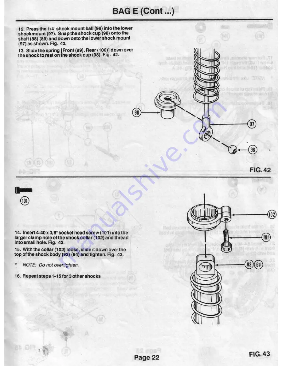
Page 25: ...spring Front 99 Rear 100 down over the shockto rest on the shock cup 98 Fig 42 14 lnsert4 40x 3 8 socket head screw 101 into the larger clamp hole ofthe shock collar 102 and thread into small hole Fig 43 15 Withthe collar 102 loose slide it down overthe top ofthe shock body e3 94 and tighten Fig 43 NOTE Do not overtighten 16 Repeat steps 1 15for3 other shocks Page 22 FIG 42 FIG 43 ...

Page 26: ...ocktower 24 Fig 44 B 19 Securetop ofshock with 4 40nylon nut 75 Fig 44 1 8 I 0 20 Forthefrontshocks align 1 4 shockmount ball 98 in lowershockmount 97 withInsideholein front A Arm 5 Fig 45 A 21 Thread a 4 40x1 Z sockethead screw 18 into front ofA arm 5 through 1 4 shockmountball 98 and intoothersideofA arm 5 Fig 45 A 22 Place shockbody 93 onfrontshockmountin frontshocktower 2 and secure with 4 40 ...

Page 27: ...ngs 80 In each front wheel 107 Fig 46 0 4 Repeat step 2 on reartires 1 06 and rear wheels 108 Fig 47 5 Tiresand wheelsare nowready forinstallation on axles Front 29 Rear 8S Install rear wheels 108 taking careto align 1 16 x7 16 solid pin 40 with grooveInrear wheel 108 Secureall wheels Front 107 Rear 108 with a 1G 32nylon nut 109 Fig 46 47 NOTE Be careful not to overtighten and bind front wheels wi...

Page 28: ...or gear cover on Page 26 4 Removeantenna mount cap 18 from antenna mount 19 on chassis 9 5 Thread antenna wirethroughtube 115 sothat 3 4 ofthewire extends out sidethetube 115 Fig 49 6 With wire positioned into slotinantenna mount 18 place end ofantenna tube 115 intoantenna mount 18 making surewireisfreeandtube 115 is secure Fig 49 7 Slideantenna mountcap 18 down overantenna tube 115 and snap ontoa...

Page 29: ...d paints Apply painttothe Inside ofthe bodyand the underside of wing Removethetape forthe nextcolor etc Tryto usethe darker colorsfirst Ifyou usea dark coloraftera lightercolor applya coat ofwhite over the lighter colorfirst Trim shaded por tions ofwing gear cover and body Install body onto carand secure it with body clips Cutoutthe stickers you wish to useand beforeremov ingthe protective backing...

Page 30: ...othattheflat wire holding edges are pointing Inward toward each other The maletop wing button 112 isturned sothatthe large notch Is also pointing Inward asshown In Fig 52 15 Insertthe wing wire 110 fromthe backand throughthewing buttons 112 113 untilthewing lain the desired position Fig 53 16 To lockthe wing 111 in position rotatethetop wing button 112 1 4 tum clockwise untilthetabs pointfrontto b...

Page 31: ...Toe In I Toe Out Camber f DISTANCE A LESS THAN B TOE IN DISTANCE B LESS THAN A TOE OUT _ __ _ _ _ P t DIM B 11 DIM A 1 TOP VIEW NEGATIVE CAMBER I POSITIVE FRONTVIEW Page 27 ...

Page 32: ... thrust washers and holes In the center diff gear with a pipe cleaner after every weekend of racing If the proper maintenance Is followed washers and balls will have a consider ably longer life span To adjust the differential use a 5 64 allen wrench through the adjusting hole on the left side of the gear box Turn clockwise to tighten counter clockwise to loosen the adjustment screw To check the pr...

Page 33: ...ive you more steering into a turn but less out It also carries the front end higher in the bumps 2 Lighter front dampening will provide the op posite results of light front damping 3 Lighter rear dampening will make the car more agile but will also allow more weight to transfer quicker across the car This results In less traction and lifting of the inside front tire 4 Heavier rear dampening will t...

Page 34: ...AR SHOCK TOWER A 4048 FA REAR SHOCK TOWERS 2 25 SERVO SAVER A 1501 SERVO SAVER IDLER ARM 1 26 IDLER ARM A 1501 SERVO SAVER IDLER ARM 1 27 STEERING SECTOR ARM A 1510 EXTENDED SECTOR ARM W HDWE 1 28 STUDDED BALL WASHERS A 6215 4 NARROW WASHERS 10 29 FRONT AXLE A 1005 FA AXLES W NUTS 2 30 SPINDLE RIGHT A 1002 FA SPINDLES CARRIERS 2 31 SPINDLE CARRIER A 1002 FA SPINDLES CARRIERS 2 32 1 8 x 690 KING PI...

Page 35: ...ROW WASHERS 10 75 4 40 NYLON NUT A 6301 NYLON 4 40 NUTS 10 76 4 40 x 1 8 BUTTON HEAD SCREW A 6212 4 40 x 1 8 BUTTONHEAD 4 n GEAR COVER A 3003 GEAR COVER 1 78 4 40 x 1 4 FLATHEAD ALUM SCREW A 6213 4 40 J 1 4 FLATHEAD SCREW 6 79 HUB CARRIER A 2025 HUB CARRIER 2 80 3116 x 318 BUSHING A 6920 BUSHING KIT 9 81 H ARM RIGHT A 2015 H ARM SET LF RT 1 82 H ARM LEFT A 2015 H ARM SET LF RT 1 83 1 8 x 1 420 HIN...

Page 36: ...NG WIRE A 8101 WING WIRE PRE BENT 1 111 WING A 8100 STANDARD WING 1 112 MALE TOP WING BUTION A 8102 ADJUST WING BUTION SET 1 113 FEMALE BOTIOM WING BUTION A 8102 ADJUST WING BUTION SET 1 114 3mm x 8mm SOCKET HEAD A 6201 3mm x 8mm SOCKET HEAD 10 115 ANTENNA TUBE A 4002 ANTENNA KIT 1 116 ANTENNA TIP A 4003 ANTENNA TIPS 8 117 4 40 x 1 8 SOCKET HD SHLD SCW A 6200 4 40 x 1 8 SHOULDER SCREW 4 118 DUST C...

Reviews: