background image

Summary of Contents for LX-T

Page 1: ...s and tuning tips outlined in Ibis manual Being able to grasp the overall design ofyour LX T racing truck before construction will ensure a smooth assembly Take your time and pay close attention to de...

Page 2: ...T manual When you reach this 19 20 D 40 41 24 27 point in assembly install the dogbones from step 26 in the XX transmission instructions Once both dogbones are installed retum to step 28 page 20 in t...

Page 3: ...nece ryto complete certafn eectlon ofthe truck II Ia HMnllel that you open only one beg at 1 time and followthe right aequence otherwlae you mey flee dlfflcultlea In finding the right part II Is helpf...

Page 4: ...ter or the screw size that wlll paiS through the I D E cllps are sized by the shalt diameter of attachment Your LX T kit lncludH e 80 tooth 48 pitch epurgear The Internal gearbox ratio Ia 2 18 1 The e...

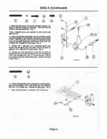
Page 5: ...head acrews 3 Flg 1 2 l llrelld In 3 r b U atud 4 Into the Inside hole of the three holes at the bottom of the thock to_ 1 TheM go on the Ita aide of the lhoc k mountt 2 Secure the ball tludt 4 with 4...

Page 6: ...Attach the body mount slide 11 to the beck llde of the body mount 12 by tlnldlng two 4 40 x 3 r cep hNd screws 13 Into the cent hoiH of the body mount elide 11 Fig 4 8 Affixthe body mount 12 tothetwo...

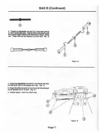
Page 7: ...a 10 Repeat tor right tide Fig 5 11 Center 1 r x 880 pin 111 In lpindle center and tcNW 5 40 Mt tcNW 20 Into Wir ofaxle 15 and up agalnat 1 l f x 880 pin 111 until anug Fig 5 1o Thread one 3 l f bell...

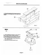
Page 8: ...o Fig 7 Note One end oltvmbucl le Ia fell Mild thle Js n m ilii B llllii i llil 0 NNW _ PUJi t u 13 Find the lhllt of a foam rtngal 3 and r move 4 from the lhllt l tac onetoamrtng 23 OVII ch baN ltud...

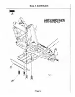
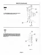
Page 9: ...BAG A Continued Page 5 14 Mount the com ed front end at aembly to the chlltlt 28 along with the front bumper 24 ual 48 32x 1 Z aluminum acrewa 25 Fig 9 Figure 9...

Page 10: ...In Fig 11 3 Thread one 1 8 ball atud 32 into each aide of steering aectorarm 33 using a gold waaher 34 Two total 4 Secwe MC torarm 33 to ldl arm 27 and bllllcrank 28 aa ahown ualng 4 40 x 1 r cap hMd...

Page 11: ...ultlltlon belOw Mike two n will now bl reflrTid to til roda Fig 12 0 IU IUII 8 f II IIII IIII D 7 sner one ldjUitlblt rod end 21 on thetil rod onto the bill ltud 32 on the MCtor 11111 33 Fig 13 1 Snep...

Page 12: ...11 PHI off blcldng from blttery box foam 341 and epply to In bottom of blttery box lid 31 12 S Cur blttery box lid 31 to bltterybox 341 Ullng 4 40 x 1 Z cap heed ecrew 38 ahown Fig 15 Note Thread8CI8...

Page 13: ...3211 1 aluminum 25 Fig 1e 15 Snap antenna mount cap 42 onto antenna mount 43 and NCtn antenna mount 43 to chaula 28 aa allown using one 11 3 r flatheed acrew 30 Be 111n that the a1ot In the antenna m...

Page 14: ...m llemount of thrlld lock lhould be UMCI Fig 1811teslde until Step 27 5 Insert one 8mm x 14mm bearing 49 Into eech side of lower bearing eeat In both gearbox halves left 50 right 51 Fig 19 8 lnltlll o...

Page 15: ...oU g belleville cone Wlaherl 63 downthe button IMI d acr 82 with thetip ofthe cone of the flnt Wllher 63 egalnlt the IMI d of the acrew 82 Fig 22 Note The belleville washers 63 are black The washerssh...

Page 16: ...ntlll oneo cent IIMr l 88 In right IIIIH of Jl box 51 10 tllllt the hMd of the 5 40 11 t 1 crew 82 txpOMCI Fig 25 21 Slide ttnec1tc1 tnd of the top II alii throuGh upptr btnlg 87 In right IIIIH of 11...

Page 17: ...ethem to the motorj llte 70 ualng thrH 4 40 x 1 3 r CIP held acrewa 71 Puah dull cover e5 over dltferentill 1dju1tment hole In left half of gHrboX 31 lnaert 3 3Z x 1 Z eplrtl pin 72 Into unlver l piv...

Page 18: ...on the allpper peel t Pllce the allpper peel 7t 1ndgNr pllfe 80 over the geart ox shaft 45 peel aide first Try to get thla laNm y 11 cl011 to center on the 1haft 45 11 poulble Carefullylnatlll the ap...

Page 19: ...I WIIrd two holes In the reer ot cheul1 28 Fig 30 2 Secure reer bllttery Rip 88 to the chelals 28 u lng two 4 40 x 3 fl llltheed ecrews 30 UN the IOI WIIrd holes In chllals 28 Fig 30 II CD 3 Thread tw...

Page 20: ...ng two 4 40 x 7 8 caph d screws 3 aa shown Fig 32 I 6 Attach r r bulkhead 89r to cha la 29 using two 8 32 x 1 2 flathead acrewa 25 In the rear and two 4 40 x 3 8 flathead screws 30 n the front Fig 33...

Page 21: ...H 11rm 101 L 102 A between rear pivot support 96 and rear bulkhead 89 Fig 35 Note The H41 rms are marked L and R in the side area behind Cfle Shock mounting holes Refer to If lustratlons to assure th...

Page 22: ...8 Insert 1 ff x 1 420 hinge pin 105 through H arm 101 102 and through upper hole of the hub carrier 104 l ig 37 19 Snap the H arm spacere 106 Into grooves on pin 105 Fig 37 Note lt aHalest If one groo...

Page 23: ...ol81 fn the rear axle 107 Fig 39 23 Ualng pllen puah a 3 3Z x 1 Z aplrol pin 72 through rNraxle 107 and uniV MI pivot 73 until pin 72 eX1enda evenly out of both sld81 of rNr axle 107 Fig 311 24 Pry un...

Page 24: ...tpllnet ol the drive thlftt male 74 female 108 Swing the H arm 101 102 up lnd lntert the male drtve theft 74 Into female drtve theft 108 Fig 418 28 Pilei 1 101m rtng 23 over Nch of the bill ltudt 4 on...

Page 25: ...odr 1 11 _P c rtrtdg1 c p 113 onCo c ertttdge body 111 Fig 43 2 Mike tour ceMdgl eM tnblllt Note Cartridges me bePfH bled at the factory 3 Pllce e drop or oil 114 on grooved end of Mo k lhtft Front 11...

Page 26: ...120 R r 121 with ciNn aoft lint free cloth Fig 47 Noto Frontshockbody 120 sshortorlhanr01ll shock body 121 10 Fllllhock body 120 121 with lhock oil 114 up to bottom of the threada t ig 47 11 lnsertlhl...

Page 27: ...dOM1 over the ahock to reet on the ahock cup 123 Fig 41 I 16 101111 I 4 40 X3 fl Clr held ICteW 13 Into the llrgwhole ofthe ahockcol r 125 lnd tlnlcllntothe nell hole Fig 48 17 Withthe c olllr 125 loo...

Page 28: ...2 on _ ahock _ to Fig 50 21 Stcuretopofahockwitha 4 40 nylon nut 127 Fig 50 0 I 0 22 For front ahocka align 1 _ ahock mount ball 122 ralla on front A m 7 8 Fig 51 23 llnecla 4 40xt cap held acr w 38 l...

Page 29: ...e front axles 15 See inset right 5 Install two 3 16 x 3 8 bearings 87 in each front wheel 130 Fig 52 6 Place front wheel 130 onto front axle 15 and secure with a 1Q 32 nylon nut 135 Note Be carefulnot...

Page 30: ...antenna lube 140 10 that 3 lf of the wire extenda outelde of tube 140 Fig 55 6 With wire poaltlonld Into elot In entenna mount 43 place end of antenna tube 1401 Into antenna mount 143 making aure wir...

Page 31: ...1nedJuatable rod end 143 onto both akiH of 1 1 Z thrNded rod 144 lT I i I Figure 56 14 Threed one 3 18 blllltud 145 Into lteerlng servo erm and secure with 1 4 40 nul 15 15 Atulch one end of the thrN...

Page 32: ...lfter I lighter Col lpply I coatOf white OWl the lighter color tnt TRIMMING AND ATTACHING BODY Trim shlded p tlona of the body 147 F rNr body mounting hole ll llke 1 3 r hole In body use dimple betwe...

Page 33: ...Toe In I Toe Out Camber DISTANCE A LESS THAN B TOE IN DISTANCE B LESS THAN A TOE OUT DIM 8 1 TOP VIEW POSITIVE CAMBER I NEGATIVE FRONTVIEW Page 29...

Page 34: ...of the lire You ellould ftnd thai the more nagatlvacombatVOII haw Intha fronL the morehigh apead you gel c re ellould be taken too mucll cauee 1ng on the roarand of the truck uoually run alloU13 dagr...

Page 35: ...Screws 1O 21 Adjustable Rod End A XXS Heavy DtAy 30 Oeg Piasllc Rod Ends 16 22 1 875 Turnbuckle A 1018 LX T Adjustable Link Set w Rod Ends 23 Foam Things A Foam Things Linkage Rings 8 24 Front Bump A...

Page 36: ...Pivots 2 74 Male Universal Drive Shaft A 3013 Molded Universal Set 75 Window Masks A 8014 LX TTruclc Body Maalcs 76 3 16 X5 16 Bearing A slS 3 16 X 5 16 Ball Bearing Slipper n Spur Gear 90T A 3910 90T...

Page 37: ...Arm 123 Shock Cup A 6023 Spring Clamps Cupe H erm 124 Shock Spring A 6152 2 5 Spring 2 6 Rate Red 2 125 Shock Collar A 6023 Spring Clamps CUps H Arm 126 H Arm Spacer A 2015 H Arm Set Left Right 127 4...

Reviews: