background image

EN

EN

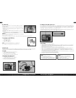
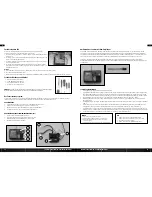
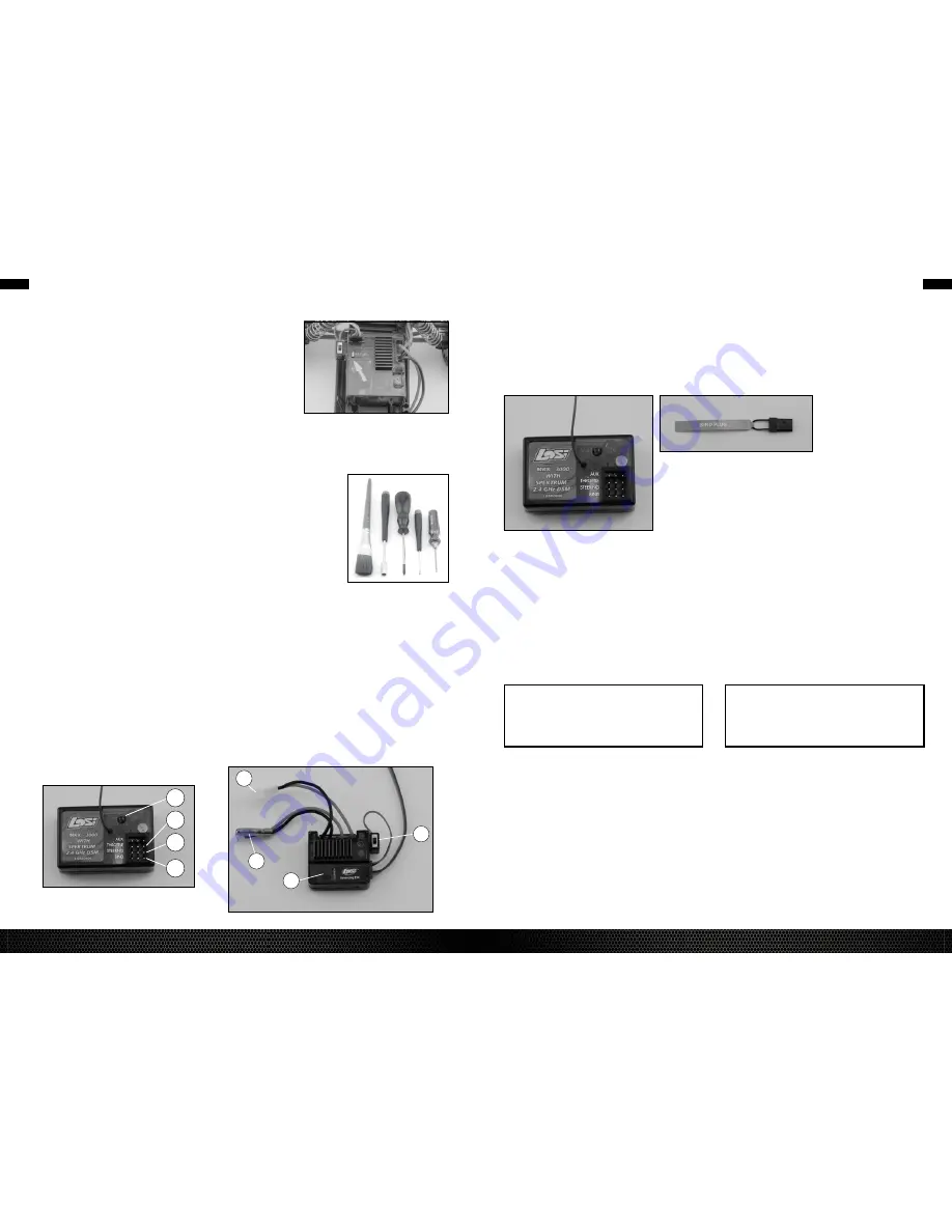
The ESc comes preset and ready for use. If for some reason you should need to reset the ESc, use 
the following instructions:
1.  Turn on the transmitter and ESc. Press the setup button—both the RED and GREEN LEDs will 

come on.

2.  Pull the throttle trigger all the way back (full speed) and press the setup button once—only the 

GREEN LED will come on.

3.  Push the trigger full forward (brake/reverse) and push the setup button once—only the RED LED 

will come on.

4.  Let the throttle trigger return to the neutral (center) position and press the setup button once more 

to save the program and exit setup mode—only the GREEN LED will be on.

IMPORTANT:

A:  If the receiver does not receive a signal from the Transmitter, the ESc will not enter program mode.
B: While in program mode, the motor will not run.
c:  If the setup button is not pressed for 20 seconds while in program mode the ESc will exit the program mode, and the data will be saved.

Resetting the ESC

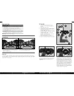
Tools and Items you Will Find handy

• 

Soft bristle brush for cleaning

• 

5.5mm nut driver for the wheel nuts

• 

#0 or #1 Phillips screwdriver

• 

LOSA99100 .050” Allen Wrench

NOTICE:

 Use only Losi tools or other high-quality tools. Use of inexpensive tools  

can cause damage to the small screws and parts used on this type of model.

4

1

2

3

1

3

2

4  

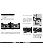
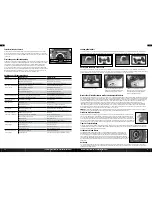
The Radio System

The following is an overview of the various functions and adjustments found on the Mini-Rock crawler radio system. Since the Mini-Rock crawler operates 
on a radio signal you control, it is important for you to read and understand about all of these functions and adjustments before driving.

ThE RECEIvER

1. 

Throttle Port: Where the Electronic Speed control (ESc) plugs in.

2. 

Steering Port: Where the steering servo(s) plugs in.

3. 

Bind Port: Used to “bind” the receiver to the transmitter.

4. 

Indicator Light: Shows that a frequency/channel is being received.

ThE ElECTRoNIC SPEEd CoNTRollER (ESC)

1. 

On/Off Switch: Powers the receiver and ESc.

2. 

Setup Button and Indicator Light: Used for resetting the ESc.

3. 

Battery Lead: connects to the battery pack for power.

4. 

Motor Lead: connects to the wire leads from the motor.

   AlWAyS

   • Turn on the transmitter before the vehicle
   • Use caution when running your vehicle near people
   • Turn both the Mini-Rock crawler and transmitter “Off” when done
   • check the battery condition of the transmitter before running

   NEvER

   • Operate the Mini-Rock crawler with low battery power
   • Run the Mini-Rock crawler through water or wet grass
   • Use chemicals to clean the chassis
   • Run the Mini-Rock crawler without a gear cover

STEPS To RE-bINd

1. 

Ensure that the transmitter and vehicle are both turned off.

2. 

 Using the supplied Bind plug (which looks like a standard receiver plug with a wire loop installed) insert or plug into the receiver slot labeled “BIND.” 
Looking down on the receiver, this slot would be below the LED and is the farthest from the LED, or nearest to the corner of the receiver. You do not 
need to remove any of the other plugs to re-bind.

3. 

 With the Bind plug installed, turn on the vehicle. You will notice a blinking orange LED within the receiver.

4. 

 Now you are ready to turn on the transmitter. You should notice on the back of the transmitter a similar blinking orange LED under the translucent cover.

5. 

 Both the receiver and transmitter blinking orange LEDs will stop blinking and become solid, indicating they have “bound” themselves together.

6. 

 Please turn off both the vehicle and transmitter to remove the Bind plug from the receiver. Failing to remove the Bind plug will cause the transmitter to 
attempt to rebind every time you turn on the vehicle and transmitter.

7. 

 Turn on both the vehicle and transmitter to ensure operation. If the transmitter does not control the vehicle, please repeat steps 1 to 6. Should this not 
correct the problem, please call Horizon Service/Repair for further assistance.

8. 

 The Bind process is complete. Your vehicle’s radio system should be ready for use.

Re-binding the Transmitter to the Receiver

The Losi

 DSM

®

 radio system included in the Mini-Rock crawler operates on 2.4GHz and provides 79 different channels, which are automatically selected 

when the transmitter and vehicle are turned on. The communication between the transmitter and receiver starts in the few seconds after the transmitter and 
vehicle are both turned on. This is called the “binding process.” The Losi DSM radio system will not interfere with previous technology radio systems that 
operate on 27MHz or 75MHz frequencies and you will not receive any interference from them. 

Although set at the factory, below are the steps required to re-bind your transmitter to the receiver should the need arise. During the bind process there is a 
unique ID from the transmitter communicated to the receiver to ensure trouble free radio operation. 

7

6

LOSI MINI-ROCK CRAWLER 

• INSTRUCTION MANUAL

LOSI MINI-ROCK CRAWLER 

• INSTRUCTION MANUAL

Summary of Contents for Mini-Rock Crawler LOSB0222

Page 1: ...Instruction Manual Bedienungsanleitung Manuel d utilisation Manuale di Istruzioni 1 18 scale ready to run MINI ROCK CRAWLER MINI ROCK CRAWLER...

Page 2: ...Thank you for choosing the Losi 1 8 Scale Mini Rock Crawler This guide contains the basic instructions for operating your new Mini Rock Crawler It is critical that you read all of the instructions in...

Page 3: ...5 Indicator Lights Green top light indicates adequate battery power Red bottom light indicates signal strength 6 Steering Trim ST TRIM Adjusts the hands off direction of the model 7 Throttle Trim TH...

Page 4: ...ing NEVER Operate the Mini Rock Crawler with low battery power Run the Mini Rock Crawler through water or wet grass Use chemicals to clean the chassis Run the Mini Rock Crawler without a gear cover St...

Page 5: ...ss Rate 1 Center servo saver arm 2 Remove servo saver arm assembly from the servo Remove the steering ball stud and install into solid servo arm 3 With servo output shaft still centered install solid...

Page 6: ...small bleed screw at the top of the shock Slowly push the shock shaft up until it stops Excess fluid should flow out of the bleed hole Slowly pull the shock shaft halfway back and replace the bleed s...

Page 7: ...EN EN 13 12 LOSI MINI ROCK CRAWLER INSTRUCTION MANUAL LOSI MINI ROCK CRAWLER INSTRUCTION MANUAL...

Page 8: ...EN EN 15 14 LOSI MINI ROCK CRAWLER INSTRUCTION MANUAL LOSI MINI ROCK CRAWLER INSTRUCTION MANUAL...

Page 9: ...on Case Set LOSB1426 Transmission Skid Plate Item Description LOSB1427 Center Transmission Gear Cover LOSB1428 Center Transmission Gear Set LOSB1429 Center Transmission Bearing Set LOSB1430 Bearing 4x...

Page 10: ...state to state Horizon reserves the right to change or modify this warranty at any time without notice WARRANTY SERVICES Questions Assistance and Services Your local hobby store and or place of purch...

Page 11: ...ekt befolgt werden k nnen sich m glicherweise Sachsch den UND geringe oder keine Gefahr von Verletzungen ergeben ACHTUNG Wenn diese Verfahren nicht korrekt befolgt werden ergeben sich wahrscheinlich S...

Page 12: ...ndem der Schalter auf dem Geschwindigkeitsregler in die Stellung ON EIN geschoben wird Wenn sich die Hinterr der drehen den Knopf TH Trim unten rechts vom Lenkrad justieren bis sich die R der nicht me...

Page 13: ...r und Empf nger beginnt einige Sekunden nach Einschalten von Sender und Fahrzeug Das wird als Abstimmungsvorgang bezeichnet Das Losi DSM Fernsteuerungssystem verursacht keine St rungen von lteren Fern...

Page 14: ...lichkeit 1 Den Servo Saver Arm zentrieren 2 Die Servo SaverArm Einheit aus dem Servo nehmen Den Lenkungskugelzapfen entfernen und in den massiven ServoArm einbauen 3 Wenn die Servo Ausgangswelle noch...

Page 15: ...aube an der Oberseite des Sto d mpfers entfernen Die Sto d mpferkolbenstange langsam nach oben bis zum Anschlag dr cken bersch ssiges l muss aus dem Entl ftungsloch austreten Die Sto d mpferkolbenstan...

Page 16: ...DE DE 31 30 LOSI MINI ROCK CRAWLER Bedienungsanleitung LOSI MINI ROCK CRAWLER Bedienungsanleitung...

Page 17: ...DE DE 33 32 LOSI MINI ROCK CRAWLER Bedienungsanleitung LOSI MINI ROCK CRAWLER Bedienungsanleitung...

Page 18: ...riebegeh use Satz LOSB1426 Getriebe Bodenplatte Artikel Nr Beschreibung LOSB1427 Mittiges Getriebe Zahnradabdeckung LOSB1428 Mittiges Getriebe Zahnr der Satz LOSB1429 Mittiges Getriebe Lager Satz LOSB...

Page 19: ...rizon nicht durchf hren Dies gilt auch f r Garantiereparaturen Deshalb kontaktieren Sie in einem solchen Fall den H ndler der sich mit Horizon kurz schlie en wird um eine sachgerechte Entscheidung zu...

Page 20: ...r pour avoir la certitude qu elles correspondent aux exigences de ce chargeur Lors de toute charge surveiller en permanence la temp rature du pack de batteries Toujours interrompre le processus de cha...

Page 21: ...mutateur sur le contr leur de vitesse sur la position On Si les roues arri re tournent r gler le bouton TH Trim situ en bas droite du volant jusqu ce qu elles s arr tent Pour aller en avant tirer la g...

Page 22: ...is sous tension La communication entre l metteur et le r cepteur commence dans les quelques secondes qui suivent la mise sous tension de l metteur et du v hicule C est ce que l on appelle le processus...

Page 23: ...umis des charges importantes Mouvement sans restriction Moins de mouvement 1 Centrage du bras du sauve servo 2 D solidariser et d poser l ensemble mont bras du sauve servo du servo Retirer le pivot ro...

Page 24: ...u e sur la partie sup rieure de l amortisseur Pousser lentement l arbre de l amortisseur vers le haut jusqu ce qu il s arr te L exc dent de liquide doit s couler par l orifice de purge Tirer lentement...

Page 25: ...FR FR 49 48 LOSI MINI ROCK CRAWLER Manuel d utilisation LOSI MINI ROCK CRAWLER Manuel d utilisation...

Page 26: ...FR FR 51 50 LOSI MINI ROCK CRAWLER Manuel d utilisation LOSI MINI ROCK CRAWLER Manuel d utilisation...

Page 27: ...6 Plaque de protection de la transmission Article Description LOSB1427 Capot d engrenage de la transmission centrale LOSB1428 Pignons de transmission centrale LOSB1429 Jeu de roulement de la transmiss...

Page 28: ...ns de plus besoin d une adresse compl te d un num ro de t l phone pour demander des renseignements et d une adresse de courriel Garantie et r parations Les demandes en garantie seront uniquement trait...

Page 29: ...e le istruzioni di base per il funzionamento del nuovo Mini DT essenziale leggere tutte le istruzioni in modo da utilizzare il modello correttamente ed evitare eventuali danni Utilizzare unicamente at...

Page 30: ...e sul controllo di velocit in posizione On Se le ruote posteriori girano regolare la manopola TH Trim posta in basso a destra del volante fino al loro arresto Per andare avanti tirare indietro il gril...

Page 31: ...ente quando il trasmettitore e il veicolo vengono accesi La comunicazione tra il trasmettitore e il ricevitore inizia pochi secondi dopo l accensione del trasmettitore e del veicolo Questo chiamato pr...

Page 32: ...asso pieno Meno tasso 1 Centrare il braccio del salva sterzo 2 Rimuovere l assemblaggio del braccio del salva sterzo dal servo Rimuovere il perno a sfera e installarlo nel braccio compatto del servo 3...

Page 33: ...n 0 per rimuovere la piccola vite di sfiato nella parte superiore dell ammortizzatore Spingere leggermente l albero dell ammortizzatore finch si ferma Il fluido in eccesso dovrebbe uscire dal foro di...

Page 34: ...IT IT 67 66 LOSI MINI ROCK CRAWLER Manuale di Istruzioni LOSI MINI ROCK CRAWLER Manuale di Istruzioni...

Page 35: ...IT IT 69 68 LOSI MINI ROCK CRAWLER Manuale di Istruzioni LOSI MINI ROCK CRAWLER Manuale di Istruzioni...

Page 36: ...ggiamento trasmissione centrale LOSB1426 Piastra del pattino di trasmissione Articolo N Descrizione LOSB1427 Coperchio del cambio centrale LOSB1428 Set coperchio del cambio centrale LOSB1429 Set cusci...

Page 37: ...pellare un rivenditore che si metter in contatto subito con Horizon per prendere una decisione che vi possa aiutare nel pi breve tempo possibile Manutenzione e riparazione Se il prodotto deve essere i...

Page 38: ...2013 Horizon Hobby Inc DSM Losi and the Horizon Hobby logo are registered trademarks of Horizon Hobby Inc All other trademarks service marks or logos are property of their respective owners...

Reviews: