background image

GETTING STARTED

• 

Turn on the transmitter before the vehicle

• 

Use caution when running your vehicle near people

• 

Turn both the Mini-Slider and transmitter “Off” when done

• 

Check the battery condition of the transmitter before running

• 

Operate the Mini-Slider with low battery power

• 

Run the Mini-Slider through water or wet grass

• 

Use chemicals to clean the chassis

• 

Run the Mini-Slider without a gear cover

4

ALWAYS

NEVER

STEP


4

STEP


5

STEP


6

Off/On

St.Trim

Th.Trim

Left

Right

Brake/Reverse

Forward

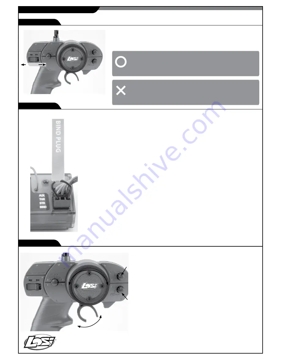
Always turn on the transmitter first by sliding the switch on the left side of 
the wheel from left to right. The small red and green lights above the 
switch should both light up. If not ,you need to check for low or incorrectly 
installed batteries.

Although set at the factor

y

, below are the steps required  to re-bind your transmitter to 

the receiver should the need arise.  During the bind process there is a unique ID from 
the transmitter communicated to the receiver to ensure trouble-free radio operation.

Steps to Re-Bind
1. 

Ensure that the transmitter and vehicle are both turned o

ff.

2. 

Using the supplied Bind plug (which looks like a standard receiver plug with a wire 

loop installed) insert or plug into the receiver  slot labeled “BIND”.  Looking down on the 
receiver this slot would be below the LED and is the  farthest from the LED, or nearest to 
the corner of  the receive

r.

Note: you do not need to remove any of the other plugs to re-bind.

3.

With the Bind plug installed, turn on the vehicle.Notice a blinking Orange LED within 

the receive

r.

4.

Now you are ready to turn on the transmitte

r

.  

Y

ou should notice on the back of the 

transmitter a similar blinking Orange LED under the translucent cove

r.

5.

 Both the receiver and transmitter blinking Orange LED

s will stop blinking and become 

solid, indicating they have “bound” themselves togethe

r

.  

6. 

Please turn o

f

f both the vehicle and transmitter to remove the Bind plug from the 

receive

r

.  Failing to remove the Bind plug will cause the transmitter to attempt to rebind 

every time you turn on the vehicle and transmitte

r

.  

7. 

T

urn on both the vehicle and transmitter to ensure operation.  If the transmitter does 

not control the vehicle, please repeat steps 1 to 6.  Should this not correct the problem, 
please call Horizon Service/Repair for further assistance. 

8. 

The Bind process is complete.  

Y

our vehicle

s radio system should be ready for use.

Once the transmitter has been turned on, turn on the Mini-Slider 
by sliding the switch on the speed controller to the “On” position. 
If the rear wheels turn, adjust the “TH. 

T

rim” knob located to the 

lower right of the steering wheel until they stop. 

T

o go forward, 

pull the trigger back. If you should need reverse, wait for the 
model to stop then push the trigger forward. When going forward 
the model should move in a straight line. If not, adjust the “S

T.


TRIM” so that it tracks 

in


a

 straight 

line

 without having 

to

 turn 

the


steering wheel. After you are have finished, turn the Mini-Slider 

of

FIRST 

by sliding the switch to the “OFF” position. After the 

model has been turned o

f

f, turn o

f

f the transmitte

r

. If you wish to 

clean your Mini-Slide

r

, use compressed air and/or 


a soft 

paintbrush to remove dust and dirt. 

NEVER 

use chemicals or 

anything wet as it can cause damage to both electronics and 
plastic parts. 

Summary of Contents for Mini Sprint

Page 1: ...l supervision for drivers under 14 It is critical that you read all of the instructions in order to operate your model correctly and avoid unnecessary damage Please take a moment to look over all the...

Page 2: ...t in product malfunction electrical issues excessive heat FIRE and ultimately injury and property damage Read all safety precautions and literature prior to use of this product Never leave the battery...

Page 3: ...all four 4 AA batteries into the battery holder Pay close attention to the correct direction of the positive and negative ends as marked in the tray Once all 4 batteries have been installed reinstall...

Page 4: ...Now you are ready to turn on the transmitter You should notice on the back of the transmitter a similar blinking Orange LED under the translucent cover 5 Both the receiver and transmitter blinking Ora...

Page 5: ...e servo gears Motor doesn t run Motor plugs loose Plug in completely Motor wire broken Repair or replace as needed ESC damaged Call Electronics Tech ESC gets hot Motor over geared Put smaller pinion o...

Page 6: ...e following is an overview of the various functions and adjustments found on the Mini Sprint radio system Since the Mini Sprint operates on a radio signal you control it is important for you to read a...

Page 7: ...load protection When the motor is stalled the ESC will automatically shut off the power output with the red LED flashing for 30seconds After 30 seconds the ESC will return to normal operation Note The...

Page 8: ...e ESC will return to the Battery Selection mode as mentioned above ESC Mode Selection During normal operation GREEN LED indicates the ESC is in the motor off position Forward Reverse Mode GREEN LED is...

Page 9: ...nd themselves together Please turn off both the vehicle and transmitter to remove the Bind plug from the receiver Failing to remove the Bind plug will cause the transmitter to attempt to rebind every...

Page 10: ...rotating the knob counterclockwise to the left For sharper or additional steering try turning the knob clockwise to the right Less Rate Full Rate Increase Slip Reduce Slip The Mini Sprint is equipped...

Page 11: ...ge plastic sun gear and the bevel gears on either side of it You can use the removed differential assembly as a guide for putting together the replacement unit a little Team Losi Te on grease LOSA3066...

Page 12: ...nd the mount to pry it loose Make sure you remove any left over foam or adhesive before remounting with common servo tape or hobby type foam tape If you are replacing the spur gear with one of a diffe...

Page 13: ...product as authorized for sale and use are USA Belgium Canada Denmark Finland France Germany Italy Netherlands Spain Sweden UK Changes or modi cations not expressly approved by the party responsible f...

Page 14: ...If you have any issue with a battery please contact the appropriate Horizon Product Support Department WARRANTY Inspection AND Repairs To receive warranty service you must include your original sales...

Page 15: ...by Inc Champaign IL USA July 04 2010 Steven A Hall Vice President International Operations and Risk Management Horizon Hobby Inc DECLARATION OF CONFORMITY in accordance with ISO IEC 17050 1 No HH20100...

Page 16: ...trical and electronic equipment The separate collection and recycling of your waste equipment at the time of disposal will help to conserve natural resources and ensure that it is recycled in a manner...

Reviews: