background image

10

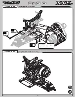
Slipper Spring

A3125

Motor Guard

A4123

Slipper Plate

A3132

Slipper Pad

A3123

Spur Gear, 78T

A3981

Spring Spacer

A3124

A3135

Spring Retaining

Washer

Gear Cover

A3042

A3043

Gear Cover Plug

Pinion Gear

(Not Supplied)

Motor

(Not Supplied)

When setting the gear mesh, leave a small amount of back-

lash for proper function. Too much backlash will cause fail-
ure, so be sure to check the mesh at different points in the 
rotation of the Spur Gear. 

BAG D

BAG D

Slipper Clutch Installation

STEP D-03

‰

Motor Installation

STEP D-04

‰

3mm x 6mm

x2

1/8” x .030”

x2

4-40 x 3/8”

x3

L 4-40 x 1/4”

x1

4-40 x 1/4”

x2

Summary of Contents for XXX-CR

Page 1: ......

Page 2: ...Yes on Tower 3 Pivot 0 Hubs 2 23mm Dogbones just under level 1 Center Steel Dogbones Steel w Shims None 27 5wt 56 Pink 170 1 A Spacer 120 1 1 32 030 Spacer 2 B 3 Ball Stud Washers 1 Inside Short Stan...

Page 3: ...In some cases extra hardware has been supplied for parts that may be easy to lose Components used in each step are identified by their relative LOSA Number and the component s name With the exception...

Page 4: ...x 3 8 A6916 2 5mm x 12mm Solid A6407 1 8 x 1 32 0325 A2127 1 8 x 1 16 0625 A5050 1 8 x 140 A A5015 3 16 x 140 A3033 3 32 x 050 A1122 L 4 40 x 3 16 Mini A6306 L 4 40 x 1 4 A6308 L 10 32 x 3 8 A6303 4...

Page 5: ...D Shafts and pins are designated by type Roll Solid and referenced by diameter x length Washers Spacers and Shims are described by inside diameter or the screw size that will pass through the inside...

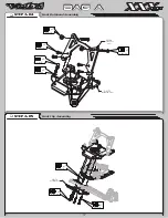
Page 6: ...2 A9956 Hinge Pin Brace Tighten the 6 40 x 5 16 Nut all the way down and then loosen it 2 full turns Steering Assembly STEP A 01 Kickplate Assembly STEP A 02 Front Suspension Assembly STEP A 03 BAG A...

Page 7: ...A4122 Bulkhead Front A4118 Front Bumper Front Bulkhead Assembly STEP A 04 BAG A BAG A Front Clip Assembly STEP A 05 Std 3 8 x2 4 40 x 3 8 x4 4 40 x 3 4 x2 4 40 x 1 4 x2 Ball Stud x2 4 40 x 7 8 x2 4 4...

Page 8: ...at wrench to hold the Turnbuckle while installing the Ball Cups Be sure to install the assembled Tierod onto the car with the groove next to the center square section on the driver s left side for eas...

Page 9: ...is com plete to ensure proper alignment Servo Manufacturer Make Model Mount Position Servo Horn JR All DZ9000T S DOES NOT FIT 1 23T Airtronics 94357Z 94358Z 94649Z 94360Z 94452Z 94758Z 94737Z 94738Z 3...

Page 10: ...4in Steering Link The Steering Link length will vary de pending on the brand and model of Servo used This length is only a starting point and will most likely need to be adjusted in Step F 01 BAG B BA...

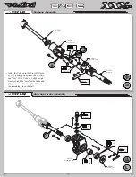
Page 11: ...g one pin of the Ball into one ear of the Yoke at a slight angle Gently spread the ears of the Yoke and slip the second ear of the Yoke over the remaining pin on the ball BAG C BAG C Dogbone Assembly...

Page 12: ...ith dots to designate the orientation Note that 1 dot is for the left and 2 dots is for the right side BAG C BAG C Rear Suspension Assembly STEP C 03 Rear Bulkhead Assembly STEP C 04 Rear Plate Assemb...

Page 13: ...old the Turnbuckle while installing the Ball Cups Be sure to install the assembled Tierod onto the car with the groove next to the center square section on the driver s left side for easier adjustment...

Page 14: ...fter Diff Balls are installed to cover the Diff Balls when the Diff is assembled Assemble the Diff and tighten until some resis tance is felt see the Final Checklist and Setup Guide for final Diff adj...

Page 15: ...nion Gear Not Supplied Motor Not Supplied When setting the gear mesh leave a small amount of back lash for proper function Too much backlash will cause fail ure so be sure to check the mesh at differe...

Page 16: ...the Dogbone is inserted into the slot in the Outdrive before installing the Transmission BAG D BAG D Transmission Installation STEP D 05 Completed Rear Clip Assembly STEP D 06 Ball Stud x1 4 40 x 3 8...

Page 17: ...lowly tighten the Cartridge until it bottoms against the Shock Body Do not tighten all the way Slowly push Shock Shaft assembly into the Shock Body This will bleed the excess oil out of the Shock Once...

Page 18: ...hing Long A5013 Shock Bushing Short BAG E BAG E Front Shock Installation STEP E 02 Rear Shock Installation STEP E 03 Completed Front and Rear Clips STEP E 04 L 4 40 x 1 4 x2 4 40 x 1 2 x1 4 40 x 1 2 x...

Page 19: ...pe of servo used the radio settings and the Servo Horn It may be necessary to adjust this length after all radio gear is installed and the servo is cen tered properly to obtain the maximum steering th...

Page 20: ...oss Section This configuration is for use with a stick type bat tery back Using a pair of sharp scissors carefully cut the inside corners of the Tire Foams away to al low for easier mounting on the Wh...

Page 21: ...by shop Install a Tire gluing rubber band around the outside of the Tire in line with the bead to hold it onto the Wheel Now slightly pull back the tire bead from the wheel and apply a thin bead of gl...

Page 22: ...dark shading in the figure below There is an indented trim line around the Body which can be used as a guide for trimming Make four 1 4 diameter holes at the locations marked with dimples There are tw...

Page 23: ...18 A6016 Wing Mount Washer Optional Front Wing Install on top of Body and behind Shock Tower Secure with the front Body Clip Body and Wing Mounting STEP F 09 BAG F BAG F Body Clip x5...

Page 24: ...tle and brake 8 Set the transmitter steering and throttle trim The steering trim tab on the transmitter should be adjusted so that the car rolls straight when you are not touching the steering wheel s...

Page 25: ...tells you that 3 71 is the external drive ratio of the transmission Next multiply the internal drive ratio 2 43 by the external drive ratio in this case 3 71 2 43x3 71 9 02 This means that by using a...

Page 26: ...mp In front of the front tires toe inward under suspension compression will result in less off power steering and running too much bump in can make the steering feel very inconsistent This effect is o...

Page 27: ...bumps To check the ride height drop one end front or rear of the car from about a 5 6 inch height onto a flat sur face Once the car settles into a position check the height of that end of the car in...

Page 28: ..._________________________________________________________________________________________________________________ ______________________________________________________________________________________...

Page 29: ...24 24 SETUP SHEET SETUP SHEET...

Page 30: ......

Reviews: