61
63
66
CLEAR
GREASE
67
62
B
B
B
B
BA
A
A
A
AG E (Contin
G E (Contin
G E (Contin
G E (Contin
G E (Continued)
ued)
ued)
ued)
ued)
18
Figure E-7
Step E-7
Step E-7
Step E-7
Step E-7
Step E-7
Step E-8
Step E-8
Step E-8
Step E-8
Step E-8
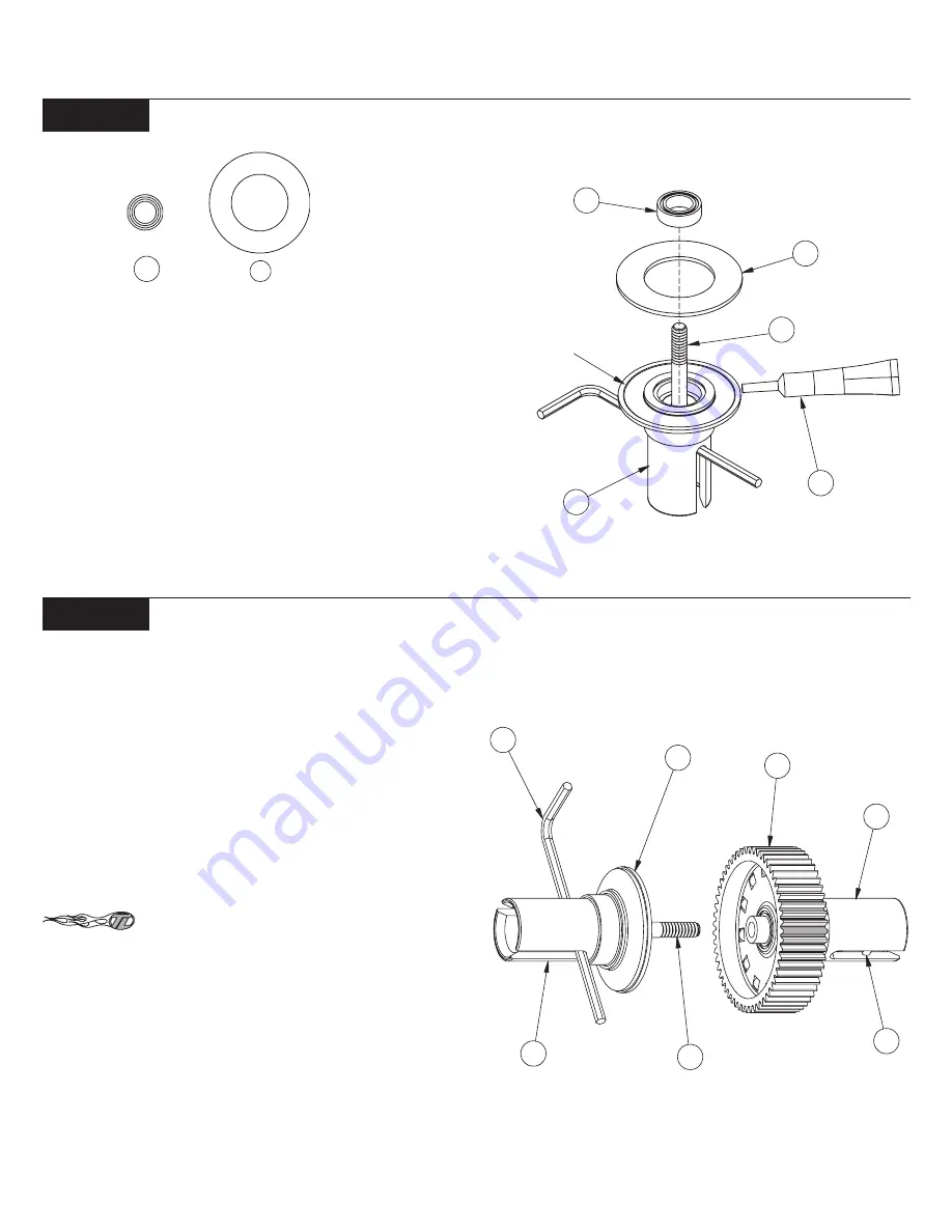
1. Locate the 5/64" Allen Wrench (59) and place it through the
slot in the Outdrive (66) containing the Diff Screw (67). Slide the
Wrench all the way against the Screw. By handling the outdrive with
the wrench inserted, the Diff Screw will be held in place while finish-
ing assembly of the differential.
2. Insert a 5mm x 8mm Bearing (63) into the female Outdrive.
Make sure that the Bearing is pushed all the way into the Outdrive.
3. Apply a small amount of clear Diff Grease (62) all the way
around the face of the outside ridge of the Outdrive. Attach a Diff
Ring (61) to the Outdrive by centering the hole in the Diff Ring over
the raised center portion of the Outdrive.
*NOTE: Only a small amount of Grease is needed, but be sure to
cover the entire face of the ridge on the Outdrive.
1. While holding the Outdrives (66)(60) with the Allen wrench
inserted, carefully place the two Outdrives together.
2 Make sure that the slot in the Diff Screw (67) is lined up with the
slot in the Outdrive (66) and that the Allen wrench is inserted in the
slot in the Diff Screw.
3. Hold the diff so that the Outdrive with the Diff Nut is pointing
up. Slowly turn the Allen Wrench and Outdrive clockwise to thread
the Diff Screw into the Diff Nut. Thread the two halves together until
the Screw just starts to snug up.
*NOTE: If the screw will not thread into the nut, make sure that
the Diff Nut is pushed all the way into the Outdrive.
When tightening the diff, tighten the Screw a little
and then “work” the Diff a little. Then tighten the Diff a little more and
“work” the Diff again. Continue this until the Diff is relatively tight.
This will ensure proper seating of all the parts in the Diff assembly.
4. Tighten the diff until the Diff Gear (64) can not be turned while
both of the Outdrives
are being held. Final diff adjustment must be
made after completion of the truck.
Figure E-8
63
61
Diff Bearing Install:
Diff Assembly:
60
57
67
64
61
59
66
Summary of Contents for XXX-NT AD2
Page 65: ......


