83
77
79
80
64
B
B
B
B
BA
A
A
A
AG E (Contin
G E (Contin
G E (Contin
G E (Contin
G E (Continued)
ued)
ued)
ued)
ued)
21
Step E-13
Step E-13
Step E-13
Step E-13
Step E-13
Step E-14
Step E-14
Step E-14
Step E-14
Step E-14
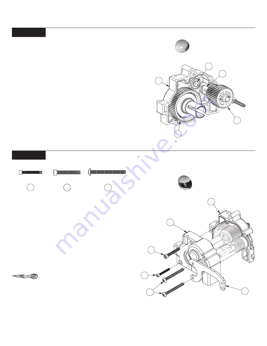
1. Insert the Brake Shaft (77) through the 3/16" x 3/8" Bearing (80)
in the left Gearbox Half (83), aligning the teeth of the Compound Gear
with those of the the Diff Gear (64) and Top Shaft (75). Push the the
Brake Shaft through the Bearing.
1. Apply a thin coat of white Assembly Grease (71) to both sets
of gears on the Compound Gear (79). This will help seal the Gearbox
once it is assembled and increase gear life.
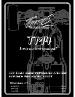
2. Carefully place the right Gearbox Half (82) over the assembled
left Gearbox Half. Be sure to align each Shaft into the Bearings in the
right Gearbox Half.
3. Thread the 2-56 x 5/8" Cap-Head Screw (85) into the lower,
rearward hole in the Gearbox Half from the right side.
Be sure you have completed Step 2, and have pre-
tapped the top three holes in the left Gearbox Half before installing
the 4-40 x 1-1/8" Button-Head Screws in Step 4.
4. Position the Aluminum Gearbox Brace (88) on the right Gear-
box Half as shown in Figure E-14. Thread two 4-40 x 1" Button-Head
Screws (87) through the Gearbox Brace and into the two holes in the
Gearbox Half.
5. Thread the 4-40 x 3/4" Cap-Head Screw (86) into the upper,
middle hole in the Gearbox Half from the right side.
Figure E-13
Figure E-14
85
Gear Box Assembly:
Compound Gear Install:
86
87
87
82
88
87
86
85
83
Summary of Contents for XXX-NT AD2
Page 65: ......


