B
B
B
B
BA
A
A
A
AG E (Contin
G E (Contin
G E (Contin
G E (Contin
G E (Continued)
ued)
ued)
ued)
ued)
22
Step E-15
Step E-15
Step E-15
Step E-15
Step E-15
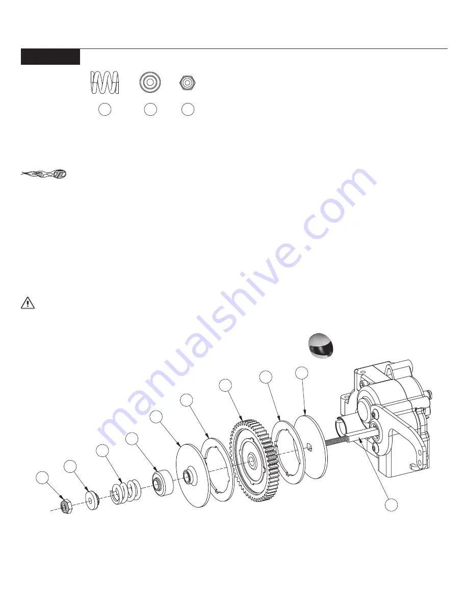
1. Slide the Slipper Backing Plate (89) over the Slipper Shaft (73), aligning the flat sections on the Slipper Shaft with the flat sections of the
Slipper Backing Plate.
Place a drop of glue to the Spur Gear before locating the slipper pad to the notches on the spur gear. This will make the assembly
of slipper easier.
2. Place the Slipper Pad (90) on one side of the Spur Gear (91) and align the notches on the Spur Gear with the notches on the Slipper Pad.
3. Place the Spur Gear, pad side first, over the Slipper Shaft. The Slipper Pad should rest against the Slipper Back Plate.
*NOTE: Ensure that the notches in the Slipper Pad remain indexed in the Spur Gear.
4. Install the second Slipper Pad to the exposed side of the Spur Gear. Again, align the notches on the Spur Gear with the notches on the
Slipper Pad.
5. Place the second Slipper Backing Plate (89) over the Slipper Shaft so that the large, flat surface of the Slipper Backing Plate rests against
the Slipper Pad.
6. Slide the Slipper Spring Adaptor (92), large side first, onto the Shaft and against the outer Slipper Backing Plate.
7. Place the gold Slipper Spring (93) over the Shaft, followed by the Spring Retaining Washer (94), small side first, and secure with the 4-40
steel Locknut (95).
IMPORTANT NOTE: Before tightening the Nut, check to see that the Slipper Pads are properly aligned with the Spur Gear on both sides.
If not, align them before proceeding.
8. Tighten the 4-40 Locknut all the way down, then back it off four full turns (e.g., 360
o
x 5). This is a good starting point for adjustment.
Final adjustment can be made later.
Figure E-15
94
95
Slipper Clutch Assembly:
89
90
91
90
89
92
93
94
95
73
93
Summary of Contents for XXX-NT AD2
Page 65: ......


