background image

5 5

negative camber can make the truck respond quicker on some tracks with hard packed surfaces.

The rear camber is used to help the truck drive through bumps in corners a little better.  Generally, run between one and two degrees of

negative camber at ride height. More negative camber will make the truck drive through bumps better, but you will usually lose a little straight

line rear traction.

FRONT TOE-IN and TOE-OUT 

is fully adjustable by changing the length of the tie rods. When adjusting toe-in, be sure to adjust both tie

rods equally so that the steering balance from left to right will remain the same. Toe-out will make the truck turn into the corner faster, but can

cause oversteer. It can also make the truck feel “wandery” exiting corners and cause the truck to hook.

Toe-in makes the truck a little easier to drive, and will make the truck more neutral feeling and more stable exiting corners.  We almost always

run about one degree of toe-in on the XXX-NT.

FRONT RIDE HEIGHT 

is an adjustment that can change the way a truck jumps, turns and goes through the bumps.  This is an adjustment

that can vary from track to track.  You should try raising and lowering the front ride height to get a feel for what it does to the handling of the

truck. The front ride height should initially be set so that the arms are level at ride height. To set the ride height, drop the front of the truck from

about 2-3 inches above the table. Lightly "work" the front suspension up and down. This will "settle" the front suspension at its natural ride

height. Working the suspension becomes important as the parts start to get dirty and worn.

Once the suspension has settled, the arms should be level. If the front end is either too high, or too low, adjust the spring collars

accordingly and check the ride height again as described above. Continue this procedure until the front ride height is adjusted to the desired

location.

REAR RIDE HEIGHT 

can change the way a truck turns, the amount of traction a truck has and the way a truck goes through the bumps.

Again, it is a good idea to play with this adjustment and get a feel for it. For most conditions, the rear ride height should be set so that the dog

bones are level with the ground. Adjust the rear ride height in the same way as described in the front ride height section.

CAMBER LOCATIONS 

on the XXX-NT are very adjustable. Although there are many holes to choose from, it is suggested that the

locations in the manual be used.  We have done extensive testing with all of these locations both on the track, and on special computer

programs, and have found the locations in the manual to be 

very consistent

 from track to track. These locations should produce the best all

around setup and work under most conditions.

REMOVING THE ENGINE 

can seem slightly difficult when you look at all of the fuel lines and linkages connected to the engine. This is

really a simple thing to do though. The easiest procedure that we have found is the following — remember to leave the engine mounts attached

to the engine: First, remove the fuel line from the fuel tank. You want to remove the line that runs to the carburetor. Remove the screw that holds

the pipe-mounting wire in place. Remove the four screws that hold the engine mounts in place. Slide the engine out of the left side of the chassis

while positioning the engine so that the short throttle linkage can be removed from the throttle arm on the carburetor.

To reinstall the engine, simply reverse the steps above.

WORKING ON THE CLUTCH 

is easier than it may seem. If you only need to work on the clutch, and don't need to remove the engine,

follow this procedure: remove the slipper adjustment nut and all of the slipper parts from the top shaft. Remove the spur gear, gear plate, and

slipper pad. Remove the clip from the clutch nut. Remove the clutch nut spacer and the outside bearing (or bushing) from the clutch bell. With

the outside bearing (bushing) removed you should be able to rotate the clutch bell slightly so that it can slide off, past the throttle servo. When

you are finished working on the clutch, install the clutch bell without the outside bearing (bushing). Once the clutch bell is in place, install the

outside bearing (bushing), followed by the clutch nut spacer. Attach the clutch nut clip. Assemble the slipper assembly according to the

manual.

The suggestions in this section are only general guidelines. There are so many variables in a racing truck that they can’t possibly be listed

in a simple tip section. Go to the track, try various combinations of setups, and get a feel for what each one does to the handling. Look for setup

updates as well as the latest hot tips in "Tech-Talk" each month in 

R/C Car

 magazine. Also check out our website, WWW.TEAMLOSI.COM

for the latest updates and additional tuning tips.

Good luck with your new XXX-NT. We’re sure you will be pleased with its superb performance.

Summary of Contents for XXX-NT Sport

Page 1: ...ips outlined in this manual Being able to grasp the overall design of your new XXX NT Sport RTR II truck before beginning any disassembly process will ensure a successful 800 0253 Service and Technica...

Page 2: ...ave subas sembly bags within them It is essential that you open only one bag at a time and follow the correct sequence otherwise you may face difficulties in finding the right part It is helpful to re...

Page 3: ...utlet towards your face The exhaust fumes can cause irritation and burning of the eyes There are a number of different brands of model fuels available We have found that fuels specially blended for R...

Page 4: ...ut 7 into the outer hex area in the servo saver bottom 1 and steering idler arm 8 as shown in Figure 2 Thread a 3 16 ball stud 11 through the outside hole in each arm into the nuts 7 and tighten Inser...

Page 5: ...ier to install the screws during assembly Figure 5 Step 12 Install a threaded insert 18 into the top of each of the two forward holes in the kickplate 14 The inserts should be installed with the hex s...

Page 6: ...on attach the servo arm 22 to the output shaft so that the arm is one spline off center in the direction shown in Figure 7A Secure the arm 22 with the servo arm screw supplied with the servo Figure 7...

Page 7: ...hassis 19 as shown in Figure 9 Insert the pin on the left servo post 24 into the hole in the servo post bushing 25 Move the servo and posts 24 slightly until both the left and right posts 24 are inser...

Page 8: ...assis brace 29 Install the fuel tank 30 on the chassis brace 29 from the bottom by pressing the three posts on the tank 30 through the three rubber grommets 28 Step 25 Place a 4 washer 23 over each of...

Page 9: ...ix 4 40 x 3 8 flat head screws 20 as shown NOTE Make sure that the pins on the top and bottom of the servo posts stay located in the holes in the servo post bushings and chassis brace and that the ser...

Page 10: ...body mount 37 to the front of each side of the front shock tower 34 so that the posts point up as shown in Figure 16 Secure the body mounts 37 by threading the screws 36 through the tower 34 and into...

Page 11: ...through the spacer 45 and the top of the spindle carrier 42 tep 11 Center the king pin 44 and secure it with two 1 8 E clips 46 With the king pin 44 still centered thread a 5 40 setscrew 47 into the...

Page 12: ...a 1 8 E clip 46 in the groove in the rear of the hinge pin 51 only Step 18 Repeat Steps 15 17 for the left spindle and carrier assembly and remaining front suspension arm 48 Step 19 Slide the front hi...

Page 13: ...he spindle carrier 42 Step 24 Attach the second camber link assembly to the left side of the truck Tip Try to mount all of the camber links so that the threads adjust in the same direction This allows...

Page 14: ...assemblies Step 26 Snap one end of a completed tie rod assembly to the ball stud 11 in the steering idler arm 8 Snap the other end to the ball stud 10 in the right spindle 40 Attach the other tie rod...

Page 15: ...tacked on the wrench into the male outdrive diff half 60 Line up the tabs on the diff nut carrier 57 with the slots in the outdrive 60 Press the parts all the way into the outdrive diff half 60 Step 6...

Page 16: ...r the diff screw 67 with the concave surface facing away from the head of the diff screw 67 Step 12 Place one of the 3mm x 8mm thrust bearing washers 69 over the diff screw 67 NOTE The thrust bearing...

Page 17: ...le holding the outdrive diff half 66 with theAllen wrench inserted carefully place the two outdrive diff halves 60 66 together Step 20 Make sure that the slot in the diff screw 67 is lined up with the...

Page 18: ...assembled from the factory Tip A small amount of liquid thread lock should be used to help to hold the setscrew securely in place If your slipper shaft was pre assembled at the factory thread lock co...

Page 19: ...supplied gearbox bearings only have one Teflon seal colored woven looking in it position the seal to the outside of the gearbox half Step 31 Insert a 1 2 x 3 4 bearing 81 into the lower bearing seat o...

Page 20: ...h shaft into the bearings in the right gearbox half 82 Step 41 Thread the 2 56 x 5 8 cap head screw 85 into the lower rearward hole in the gearbox housing from the right side Tip Be sure you have comp...

Page 21: ...the notches on the slipper pad 90 Step 48 Place the second slipper backing plate 89 over the slipper shaft 73 so that the large flat surface of the backing plate 89 rests against the slipper pad 90 S...

Page 22: ...haft 77 so that it extends evenly from both sides of the shaft 77 Step 53 Slide the brake hub 98 over the brake shaft 77 Align the groove in the brake hub 98 with the pin 78 and slide the hub 98 over...

Page 23: ...til they are just snug then back them off about 1 4 turn so the brake lever clips 101 can still be moved slightly Step 64 Insert a 3 16 E clip 103 into the groove in the end of the brake shaft 77 to r...

Page 24: ...s 105 forward and the word TOP visible at the front of the pivot block Attach the rear pivot block 104 to the chassis 19 with four 4 40 x 3 8 flat head screws 20 Figure 49 105 Figure 48 Figure 49 20 F...

Page 25: ...enly from both sides of the rear axle 109 Tip The pin can be made to press in tighter This will ensure that it stays firmly in place To do so SLIGHTLY crimp the center of the pin with heavy duty wire...

Page 26: ...rear axle 109 The pin 117 should be centered in the rear axle 109 38 114 117 115 116 31 51 46 Step 10 Slide a suspension ball 121 over a 4 40 x 1 2 cap head screw 31 and thread it into the middle shoc...

Page 27: ...river to secure the 4 40 nuts Step 18 Thread a 3 8 ball stud 38 into the center hole on each side of the shock tower 123 Figure 57 Figure 57 Figure 56 Step 15 Position the right rear arm 118 inside th...

Page 28: ...rbox 82 83 Figure 58 Figure 59 Step 20 Thread a long plastic rod end 54 onto each end of a 2 1 2 turnbuckle 124 Tighten both rod ends 54 equally until the rod is the same length as the one shown in Fi...

Page 29: ...hrought the tower 123 and battery box 125 and into the gearbox Step 25 Secure the bottom of the battery box 125 to the chassis 19 with two 4 40 x 3 8 flat head screws 20 Figure 61 Figure 60 Figure 61...

Page 30: ...d O ring 126 is inserted and is flush with the top of the cartridge body 127 snap the cartridge cap 129 onto the cartridge body 127 Step 4 Make four cartridge assemblies NOTE Cartridges in some kits m...

Page 31: ...e installing the E clip to the front shock shafts 130 the shorter of the two lengths slide a plastic spacer 120 over the front shaft 130 next to the cartridge Once the spacers are in place snap a 1 8...

Page 32: ...ely an additional 1 8 turn There should be no air in the shock as you push the shaft 130 131 in and out If there is the shock needs more oil If the shock does not compress all the way the shock has to...

Page 33: ...the dogbone is in place in the outdrive Step 26 Repeat Steps 23 25 for the left rear shock Step 27 Insert the shock end 134 of a front shock between the shock mounting rails of the front suspension a...

Page 34: ...res This glue was formulated and produced especially for this pupose IMPORTANT NOTE Allow the glue to dry thoroughly before continuing Step 5 Press a 3 16 x 3 8 bearing 114 into the inside of both fro...

Page 35: ...the crankshaft and next to the shim 153 Tip There are two shims included in the kit If the flywheel inter feres with the case of the engine add a second shim If after the engine is installed the gears...

Page 36: ...he springs 156 IMPORTANT NOTE Make sure that the clutch shoes are facing the correct direction as illustrated Position the clutch so that the shoes are separated one on top one on bottom The top clutc...

Page 37: ...should be positioned with the narrow end up as shown in Figure 78 Tip It s a good idea to use a thread lock compound on the threads of the screws in the engine mounts IMPORTANT NOTE Make sure that th...

Page 38: ...the arm rotates more in one direction loosen the nut securing the arm and re position the arm NOTE If your engine comes equipped with a slide valve car buretor the slide ball should be positioned to...

Page 39: ...ws yet Tip It s a good idea to use a thread lock compound on the threads of the screws in the engine mounts Figure 82 Figure 80 81 Figure 82 Step 19 Insert a 4 40 x 1 cap head screw 169 from the left...

Page 40: ...dy Be sure to check the gear mesh all the way around the spur gear 91 Step 26 Once the engine alignment and gear mesh are correct tighten all of the screws 173 Re check the gear mesh after all the scr...

Page 41: ...ly Secure the tuned pipe 175 to the coupler 174 by wrapping an 8 tie strap 180 around the coupler 174 and the pipe 175 and tightening Step 35 Secure the coupler 174 to the header 171 by wrapping an 8...

Page 42: ...em into the rectangular slot in the chassis brace 29 as shown Insert the cut end of the tubing into the inside small hole in the tuned pipe 176 This fuel line will serve as the fuel tank pressure line...

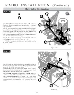
Page 43: ...should be mounted so that it is at least 1 8 above the chassis 19 and the antenna is to the front of the truck Step 3 Plug the steering servo into the slot marked Channel 1 or Function 1 on the receiv...

Page 44: ...so that the power lead is to the right side of the chassis Cut two small pieces of the battery spacer foam 185 to fit inside the battery box 125 on each side of your battery pack The foam 185 should...

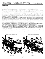
Page 45: ...e shock and vibration from the gas engine Overtightening the screws will prohibit the grom mets from working properly 188 189 23 31 Figure 94 Figure 95 Step 13 Attach the grommets supplied with your r...

Page 46: ...off position Use a couple of small tie straps to secure the battery lead to the gearbox brace This will keep the wires away from any moving parts such as the gears throttle and brake linkages etc 189...

Page 47: ...end is towards the Z bend Step 26 Place a brake over ride spring 196 black shorter of the two springs over the wire 191 and against the over ride slider 195 Place a linkage collar 192 over the end of...

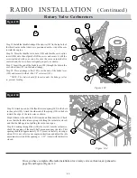
Page 48: ...97 from the bottom through the middle hole in the shorter arm of the throttle servo horn 190 Figure 102 Figure 100 Figure 102 Figure 101 Step 31 Determine which throttle servo spline insert 200 will f...

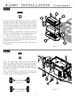
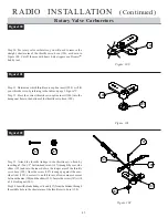
Page 49: ...collar to prevent binding Figure 103 Figure 103 Rotary Valve Carburetors Step 39 Attach one end of the throttle return spring 202 to the hole in the eyelet 199 Attach the other end of the spring 190...

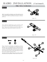
Page 50: ...d of the rod 203 so the springs are somewhat compressed and secure it with a 4 40 x 1 8 setscrew 193 The collar 192 should be positioned at the end of the rod 203 Final adjustments will be made later...

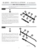
Page 51: ...rt the brake linkage Z bend 197 from the top through the middle hole in the shorter arm of the throttle servo horn 190 Figure 109 Figure 107 Figure 109 Figure 108 Step 31 Determine which throttle serv...

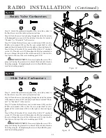
Page 52: ...193 NOTE The slider should fit loosely under the linkage collar to prevent binding Figure 110 Figure 110 Slide Valve Carburetors Step 39 Attach one end of the throttle return spring 202 to the hole i...

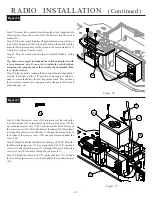
Page 53: ...er 102 rests in the forward position against the brake caliper Loosen the setscrew 193 in the collar 192 at the rear of the brake linkage wire 197 and move the collar 192 until the linkage spring 196...

Page 54: ...adio manufacturer s instructions for reversing the servos and correct the steering servo Step 49 Without touching the transmitter the front tires should be pointing straight Slight adjustments can be...

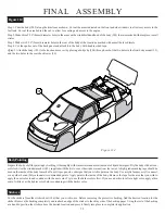
Page 55: ...of liquid detergent Dry the body with a clean soft cloth Use the window masks 185 supplied with the kit to cover the window areas from the inside Ahigh grade masking tape should be used on the inside...

Page 56: ...nding radio system If using alkaline batteries a fresh set should operate the radio system for at least 1 2 hours of running without a problem The length of time that a receiver battery pack s charge...

Page 57: ...the slot in the outdrive and placing the small Allen wrench through both slots Now slowly turn the left rear tire clockwise about 1 8 turn As long as the diff screw was held in place with theAllen wr...

Page 58: ...re very adjustable Although there are many holes to choose from it is suggested that the locations in the manual be used We have done extensive testing with all of these locations both on the track an...

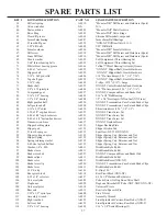
Page 59: ...end A 1615 Short Ball Cups and Threaded Rod 27 4 40 x 5 8 threaded rod A 1615 Short Ball Cups and Threaded Rod 28 Rubber tank mounting grommet A 9313 Fuel Tank Mounting Set 29 Chassis brace A 4021 XX...

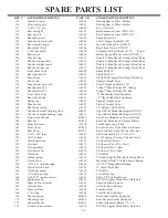
Page 60: ...20 XXX NT Transmission Case Set and Brake Clips 84 3 16 x 015 shim A 6230 ShimAssortment 3 16 1 4 1 2 85 2 56 x 5 8 cap head screw A 2921 XXX NT Trans Screw Set 86 4 40 x 3 48 cap head screw A 2921 XX...

Page 61: ...ed shock spring A 5152 2 5 Spring 2 6 Rate Red 142 Top shock mount bushing short A 5013 Upper Shock Mount Bushings all XXX 143 Top shock mount bushing long A 5013 Upper Shock Mount Bushings all XXX 14...

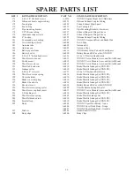
Page 62: ...415 XXX NT Servo Mounts Arms and Switch Mount 190 Throttle servo horn A 9415 XXX NT Servo Mounts Arms and Switch Mount 191 Throttle Z bend wire A 9410 Brake Throttle Linkage Set XXX NT 192 Linkage col...

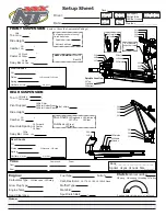
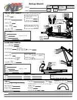
Page 63: ...r o Ride Height Caster Stock Other o Sway Bar No Yes size Front Shocks Piston Standard Drilled Spring Oil Limiters Inside Outside 1 2 3 4 A B C of washers under ball stud of washers under steering tie...

Page 64: ...r o Ride Height Caster Stock Other o Sway Bar No Yes size Front Shocks Piston Standard Drilled Spring Oil Limiters Inside Outside 1 2 3 4 A B C of washers under ball stud of washers under steering tie...

Reviews: