AX48-120 Flange Facing Machine
26
5.2.2 Mounting base installation
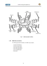
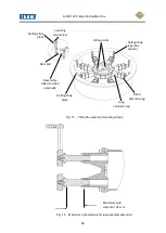
The mounting base assembly consists of a central support hub, short and long
extension legs, dual threaded collars, ram bolts and jaw assemblies with setting
straps. When using the correct configuration of extension legs the base can be
located in the flange bore and locked in position by tightening the jaws against the
wall of the bore. The base is fitted to the flange as follows:
DO NOT ATTEMPT TO MANUALLY LIFT THE BASE ASSEMBLY ALWAYS USE
A MECHANICAL LIFTING DEVICE.
ALWAYS USE SETTING STRAPS WHEN INSTALLING THE MOUNTING BASE.
1. Observe all Warnings and Cautions; refer to Sections 3 and 5.1.
2. Measure the diameter of the flange face to be machined. Ensure that the
diameter falls within the operating parameters of the machine.
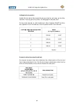
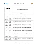
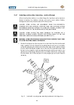
3. Measure the flange bore and select the correct base / extension configuration to
suit the flange bore diameter (refer to table Fig. 12). Before assembly ensure
that the mating faces between the base and extensions are clean. When
assembled make sure all securing screws are tight and the assembly is firmly
locked together to ensure rigidity during the machining operation.
CAUTION: WHEN LOCATING THE BASE IN A FABRICATED PIPING SYSTEM
CHECK FOR ANY WELD BEADS AND FLANGE-TO-PIPE MISALIGNMENTS
WITHIN THE PIPE AND FLANGE BORES THAT COULD PREVENT THE BASE
FROM CLAMPING SECURELY.
4. Fit the jaw assemblies into the threaded collars (2 per collar). Screw the thin
locking nut and screw each ram bolt (refer to Fig. 13) fully home.
5. Measure from the centre of the base and, using the 46mm open ended spanner
on the ram bolt hexagons, position the jaw pad face 5mm (0.25") less than the
radius of the flange bore. Repeat on all eight legs.
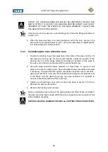
DO NOT SCREW THE JAW ASSEMBLY OUT MORE THAN THE MAXIMUM
SAFE DISTANCE OF 105 MM (refer to Fig 14).
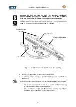
6. Screw two 25mm AF hexagon section setting strap legs to each jaw unit (refer to
Fig 13) and attach the setting strap plate, secure with two cap head screws.
Partially screw out the grub screw in the centre of the plate to ensure it does not
protrude below the plate.
7. Attach lifting cables to the four eyes (refer to Fig 13) on the base unit and
carefully position the base assembly within the flange bore allowing the setting
strap plates to rest on the flange and take the weight of the assembly.
Summary of Contents for SILK AX48-120
Page 51: ...AX48 120 Flange Facing Machine 50 Fig 26 Mast and turntable assembly sheet 1 ...
Page 52: ...AX48 120 Flange Facing Machine 51 Fig 27 Mast and turntable assembly sheet 2 ...
Page 55: ...AX48 120 Flange Facing Machine 54 28 Surfacing arm assembly sheet 1 ...
Page 56: ...AX48 120 Flange Facing Machine 55 Fig 29 Surfacing arm assembly sheet 2 ...
Page 59: ...AX48 120 Flange Facing Machine 58 Fig 30 Gearbox assembly ...
Page 62: ...AX48 120 Flange Facing Machine 61 Fig 31 Base assembly ...
Page 64: ...AX48 120 Flange Facing Machine 63 Fig 32 Toolpost assembly ...
Page 66: ...AX48 120 Flange Facing Machine 65 Fig 33 Base centraliser ...
Page 68: ...AX48 120 Flange Facing Machine 67 Fig 34 Counter balance ...
Page 71: ...AX48 120 Flange Facing Machine 70 TYPES OF TOOL BIT FOR GENERAL PURPOSE AND FINE FINISH ...
Page 72: ...AX48 120 Flange Facing Machine 71 TOOLS FOR V GROOVE PLUNGE MACHINING ...
Page 76: ...AX48 120 Flange Facing Machine 75 APPENDIX C V GROOVE MEASUREMENT ...
Page 77: ...AX48 120 Flange Facing Machine 76 ...
Page 78: ...AX48 120 Flange Facing Machine 77 APPENDIX D AIR MOTOR MANUFACTURERS INFORMATION ...
Page 79: ...AX48 120 Flange Facing Machine 78 ...
Page 80: ...AX48 120 Flange Facing Machine 79 ...
Page 81: ...AX48 120 Flange Facing Machine 80 ...
Page 82: ...AX48 120 Flange Facing Machine 81 ...
Page 83: ...AX48 120 Flange Facing Machine 82 ...

