


AX48-120 Flange Facing Machine
45
Removing the gearbox can be made easier with the surfacing arm removed (see
section 7.4.4) but it is not essential to the operation
To remove:
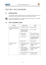
4. Observe all Warnings and Cautions; refer to sections 3.1 and 7.4.
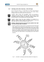
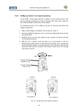
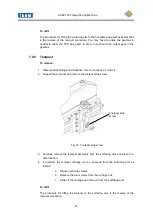
5. Push both selectors on the gearbox fully in i.e. the direction selector to the 'IN'
position and the feed selector to the 'N' position (see Fig. 5).
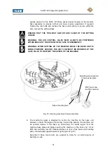
6. Position the surfacing arm so that equal amounts extend from the turntable.
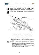
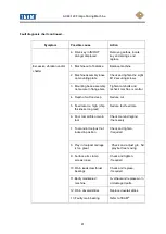
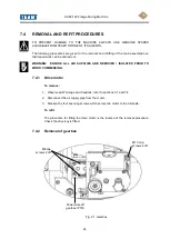
7. Remove 2 off M6 cap head screws from the PTO box (power take off); the
screws located in the slots of the PTO box lid (see Fig. 21) and the 4 off M10
cap head screws from the gearbox.
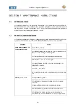
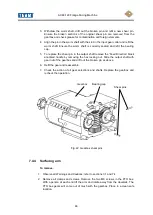
8. Firmly grip the gearbox in your right hand and with your left hand hold the PTO
box, ensuring the keeper plate is secured into the gearbox as this prevents the
output shaft from pulling out of the gearbox as it is eased away from the hub. Do
not allow the traverse direction selector to pull out of its position or this may
result in the spring loaded drive key being lost or displaced. Pull both assemblies
away from the mounting bracket. When the gearbox is clear of the mounting
plate it can be detached from the PTO box assembly.
9. Draw the gearbox assembly off the location dowels and clear of the input and
output support bushes.
10. Place in a clean safe location.
11. If the drive key becomes displaced it will be necessary to remove the selector
shaft and gears. To do this remove the black anodised handle and securing
nuts, remove the keeper plate and securing screw before withdrawing the shaft
from the gearbox (consult the gearbox drawing in parts list) and locate the drive
key. Inspect the springs and replace if any damage is visible.
To refit
To refit follow the removal procedure above in reverse. Do not forget the gear
selector shaft stop sleeve. When inserting the sub-assembly into the gearbox
rotate the gears on the shaft to allow them to mesh more easily. Refit the keeper
plate and securing screw.
Do not over tighten the M6 screws securing the PTO box.
7.4.3 Replacement of shear pins
To replace either shear pin follow the procedure:
1. Remove the gearbox as described in section 7.4.2. The shear pins will be
found in the worm shaft and in the output shaft.
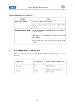
2. To replace a broken shear pin in the worm shaft unscrew the three retaining
screws and remove the bearing cap.
Summary of Contents for SILK AX48-120
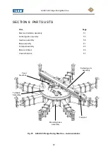
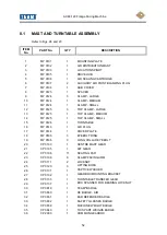
Page 51: ...AX48 120 Flange Facing Machine 50 Fig 26 Mast and turntable assembly sheet 1 ...
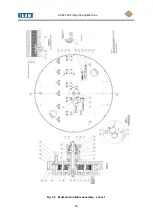
Page 52: ...AX48 120 Flange Facing Machine 51 Fig 27 Mast and turntable assembly sheet 2 ...
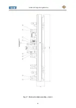
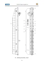
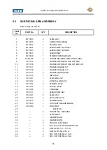
Page 55: ...AX48 120 Flange Facing Machine 54 28 Surfacing arm assembly sheet 1 ...
Page 56: ...AX48 120 Flange Facing Machine 55 Fig 29 Surfacing arm assembly sheet 2 ...
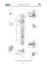
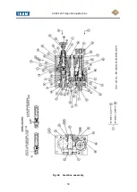
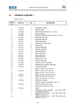
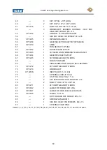
Page 59: ...AX48 120 Flange Facing Machine 58 Fig 30 Gearbox assembly ...
Page 62: ...AX48 120 Flange Facing Machine 61 Fig 31 Base assembly ...
Page 64: ...AX48 120 Flange Facing Machine 63 Fig 32 Toolpost assembly ...
Page 66: ...AX48 120 Flange Facing Machine 65 Fig 33 Base centraliser ...
Page 68: ...AX48 120 Flange Facing Machine 67 Fig 34 Counter balance ...
Page 71: ...AX48 120 Flange Facing Machine 70 TYPES OF TOOL BIT FOR GENERAL PURPOSE AND FINE FINISH ...
Page 72: ...AX48 120 Flange Facing Machine 71 TOOLS FOR V GROOVE PLUNGE MACHINING ...
Page 76: ...AX48 120 Flange Facing Machine 75 APPENDIX C V GROOVE MEASUREMENT ...
Page 77: ...AX48 120 Flange Facing Machine 76 ...
Page 78: ...AX48 120 Flange Facing Machine 77 APPENDIX D AIR MOTOR MANUFACTURERS INFORMATION ...
Page 79: ...AX48 120 Flange Facing Machine 78 ...
Page 80: ...AX48 120 Flange Facing Machine 79 ...
Page 81: ...AX48 120 Flange Facing Machine 80 ...
Page 82: ...AX48 120 Flange Facing Machine 81 ...
Page 83: ...AX48 120 Flange Facing Machine 82 ...


