

AX48-120 Flange Facing Machine
84
APPENDIX E
FALL-STOP KIT
1.
TECHNICAL DESCRIPTION
Introduction
The TEAM
®
- Fall-Stop Kit has been designed using best engineering practice. Its design will
give every satisfaction provided that it is properly installed, operated and maintained in
accordance with the information contained within this manual. Take care of this manual; it is
an essential source of information for future reference.
Equipment Description
The purpose of this equipment is to prevent the machine it is fitted to from falling inside a
vessel, pipe or similar internal opening should the machine and base fixture break loose from
the work piece during use.
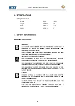
This equipment is intended for use only as a safety device when machining flanges or similar
components over unobstructed, internal openings.
This equipment is intended for use on the following standard TEAM
®
flange facing machines:
•
TEAM
®
AX48-120
This equipment is not suitable for use in overhead flanges where the machine could fall
away from, rather than into the internal opening.
This equipment is not to be used as a lifting attachment or as a counter balance.
Summary of Contents for SILK AX48-120
Page 51: ...AX48 120 Flange Facing Machine 50 Fig 26 Mast and turntable assembly sheet 1 ...
Page 52: ...AX48 120 Flange Facing Machine 51 Fig 27 Mast and turntable assembly sheet 2 ...
Page 55: ...AX48 120 Flange Facing Machine 54 28 Surfacing arm assembly sheet 1 ...
Page 56: ...AX48 120 Flange Facing Machine 55 Fig 29 Surfacing arm assembly sheet 2 ...
Page 59: ...AX48 120 Flange Facing Machine 58 Fig 30 Gearbox assembly ...
Page 62: ...AX48 120 Flange Facing Machine 61 Fig 31 Base assembly ...
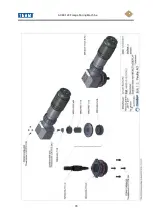
Page 64: ...AX48 120 Flange Facing Machine 63 Fig 32 Toolpost assembly ...
Page 66: ...AX48 120 Flange Facing Machine 65 Fig 33 Base centraliser ...
Page 68: ...AX48 120 Flange Facing Machine 67 Fig 34 Counter balance ...
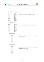
Page 71: ...AX48 120 Flange Facing Machine 70 TYPES OF TOOL BIT FOR GENERAL PURPOSE AND FINE FINISH ...
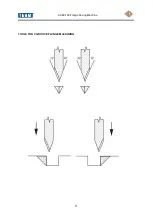
Page 72: ...AX48 120 Flange Facing Machine 71 TOOLS FOR V GROOVE PLUNGE MACHINING ...
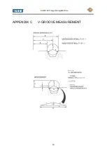
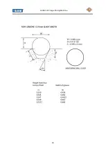
Page 76: ...AX48 120 Flange Facing Machine 75 APPENDIX C V GROOVE MEASUREMENT ...
Page 77: ...AX48 120 Flange Facing Machine 76 ...
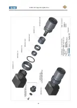
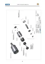
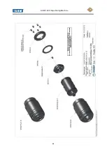
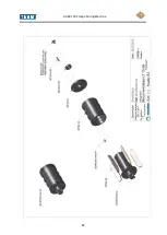
Page 78: ...AX48 120 Flange Facing Machine 77 APPENDIX D AIR MOTOR MANUFACTURERS INFORMATION ...
Page 79: ...AX48 120 Flange Facing Machine 78 ...
Page 80: ...AX48 120 Flange Facing Machine 79 ...
Page 81: ...AX48 120 Flange Facing Machine 80 ...
Page 82: ...AX48 120 Flange Facing Machine 81 ...
Page 83: ...AX48 120 Flange Facing Machine 82 ...


