background image


TMN-51T Hardware User Guide 


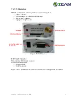
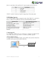
Figure 2: DB9 Female Interface 

 
Listed  below  are  the  pin  configurations  of  DB9  connector  for  all  2  communication 
standards. 


Pin  

RS232 

RS485 

Description 

Receive 

Transmit 

Ground 

Data + 

RTS 

CTS 

Data - 


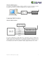
Micro Fit 3.0 Power Supply Connector 

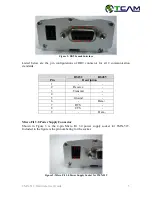
Shown  in  Figure  3  is  the  4-pin  Micro  Fit  3.0  power  supply  socket


for  TMN-51T. 

Included in the figure is the pin numbering for the socket. 


Figure 3: Micro Fit 3.0 Power Supply Socket for TMN-51T 


5    4    3    2    1 


          9    8    7    6 


1


       3    4 

Summary of Contents for TMN-51T

Page 1: ...TMN 51T Hardware User Guide contains information that is proprietary to TCAM Technology Pte Ltd No part of this document may be copied or reproduced in any form or by any means or transferred to any third party without prior written consent of TCAM Technology Pte Ltd The content of this document may be revised without prior notice ...

Page 2: ...nt 0 08A at 12VDC GPRS online no data 0 2A at 12VDC Data transmission Dimensions 86 x 54 x 25mm Weight 110g Temperature 0 to 55 C normal 20 to 70 C restricted Analog inputs Support 2 channels each capable of measuring 4 20mA analog signal System Overview TMN 51T is a plug and play RS232 to GPRS gateway It can easily retrofit a traditional serial communication system to a more advance GPRS platform...

Page 3: ...nfiguration by SMS or GPRS Remote activation by SMS or Data Call Always ON Connection Heart beat feature for socket connection Time to live timer for network checking Flexible Operation 3 methods of serial data packetization Server mode and client mode for connection Static or dynamic IP Support RS232 485 hardware interface RTOS RTC IAP UART0 UART1 AM EM NV Debug Control GPRS Modem APP SMS APP Oth...

Page 4: ... interface DB9 Female Connector 4 pin power supply socket Figure 1 TMN 51T Interface DB9 Female Connector Main interface DB9 female connector Communication standard RS232 default RS485 optional Figure 2 shows the DB9 female interface for TMN 51T including all the pin numbers DB9 Connector 4 Pin Micro Fit 3 0 Connector SIM Card Holder Red LED Radio Interface ...

Page 5: ...dards Pin RS232 RS485 Description 1 2 Receive 3 Transmit 4 5 Ground 6 Data 7 RTS 8 CTS 9 Data Micro Fit 3 0 Power Supply Connector Shown in Figure 3 is the 4 pin Micro Fit 3 0 power supply socket for TMN 51T Included in the figure is the pin numbering for the socket Figure 3 Micro Fit 3 0 Power Supply Socket for TMN 51T 5 4 3 2 1 9 8 7 6 1 2 3 4 ...
Page 6: ...blinking sequence Upon power up Start blinking after 4 second Not connected to GPRS or GSM Blink every 1 second Connected to GPRS Double blink every 4 second Data transfer via GPRS Turned on and flicker Connected to GSM modem mode Blink every 3 second In configuration mode with Center Manager LED turned off Connecting to PC For configuration TMN 51T has to be connected to a computer The diagrams b...

Page 7: ...ration in which TMN 51T is connected to a device via RS232 port transmit receive and ground pin must be connected In situation where the device is utilizing hardware flow control Ready To Send RTS and Clear To Send CTS have to be connected as well TMN 51T with RS232 interface supports hardware flow control TMAS GPRS Gate DB9 RS232 DB9 RS232 to RS485 converter RS485 Data Data TMAS GPRS Gateway Devi...

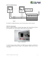
Page 8: ... The 2 analog inputs are located at the 4 pin Micro Fit 3 0 power supply socket as shown in Figure 4 below Figure 4 Analog Inputs To insert the analog signal to TMN 51T use TMN 51T power adaptor s 4 pin Micro Fit 3 0 socket connector as shown in Figure 5 The additional 2 empty holes are for the analog input Analog Inputs TMAS GPRS Gateway Meter 1 Meter n RS485 Data Data 2 ADC Channels 0 3 3V or 4 ...

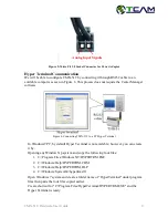
Page 9: ... Terminal In Windows7 PC by default Hyper Terminal is not available however you can create it by Opening any Window Xp system and copy the following four files 1 C Program Files Windows NT HYPERTRM EXE 2 C Windows Help HYPERTRM CHM 3 C Windows Help HYPERTRM HLP 4 C Windows System32 hypertrm dll Open Windows 7 system and create a folder name of HyperTerminal under program files then paste the four ...

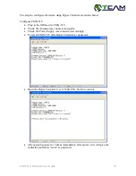
Page 10: ...e SIM card to TMN 51T Check the Antenna was connected properly Check the Power Supply was connected accordingly Power on TMN 51T after Hyper Terminal is connected Open the Hyper Terminal Use 115200 8N1 No flow control After pressing space for 3 times immediately after power on it will give the indication and enter tcam as password ...

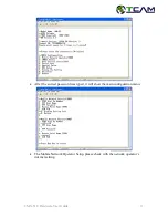
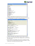
Page 11: ...TMN 51T Hardware User Guide 11 After the correct password was typed it will show the main configuration menu The Mobile Network Operator Setup please check with the network operator s internet setting ...

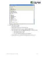
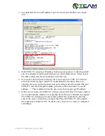
Page 12: ...his case o Packet Idle Interval will leave it as 5 which is the default value o Please remember to Set correct Packet Idle Interval for different baud rate Recommend 5 ms for 115200 Recommend 100 ms for 300 The value should be adjusted to app requirement o Packet End Character is disabled when Packet Idle Interval is not 0 ...

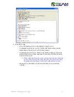
Page 13: ...munication port is set to 8000 or any number which you can get for public internet access please make sure it is the same with the one which is used on Server port Please make sure this port can be accessed from internet Either the server is direct open to the public network or the port is forward to the public network Please consult the IT administrator for this o Backup Server IP Address Center ...

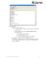
Page 14: ...t correct Last packet Idle Interval for different baud rate Recommend 5 ms for 115200 Recommend 100 ms for 300 The value should be adjusted to app requirement o Flow Control can be set as Xon Xoff Hardware or None o The TMN 51T will always goes to 115200 8N1 after power on After no correct control command is received it will goes to the GPRS gateway mode as configured ...

Page 15: ...boot and wait for a while without any input the TMN 51T will go to Data mode It will also display all the major configuration info except the ID info for secure reason After the TMN 51T get the IP address from network it will display this IP info before it switch to the working serial port setting before this TMN 51T is always working in the control mode with 115200 8N1 setting ...

Page 16: ... for few times Please do checking the correct protocol and correct port setting is used from both VSP and TMN 51T side From HyperTerminal you will see the reboot after Local IP address This is different from the previous reboot cannot get IP address If the server is down the TMN 51T will also reboot itself after TTL timer expired as it cannot identify whether it is caused by Server Down or Network...

Reviews: