4
Maintenance mode
Maintenance mode is an operation mode when all theft prevention
and service functions of Immobilizer are temporarily deactivated.
With Maintenance Mode on, entering the PIN code is not needed when
driving the vehicle, which is helpful when the car needs to be put for
maintenance in the service center. Still, in order to enter the Program-
ming mode, it is necessary to enter the PIN code.
When the ignition is turned on in Maintenance mode, a long audible
tone is sounded that reminds on the fact that the Immobilizer is in main-
tenance mode. The audible tone can be turned off for secrecy level
increase.
In order to activate or deactivate the Maintenance mode you need
to do the following:
1
Turn the ignition on Enter the PIN code and wait for confirmation
2 Press and release the Programming mode button 6 times (start
doing it no later than 10 seconds after PIN code entering).Please
wait for confirmation that you have successfully performed
the actions:
◊
1 audible signal and 1 sound trill mean that the Maintenance
mode is ON.
◊
2 audible signals and 1 sound trill mean that the Maintenance
mode is OFF.
3 Turn the ignition off.
Additional features
The Immobilizer has additional features improving the vehicle se-
curity level.
Comfort feature control
The Immobilizer can be programmed so that the vehicle’s windows
are closed when the vehicle’s security is Armed. Please see Integrator
files for supported vehicles.
Electro-mechanic hood locks control
The Immobilizer allows closing an accessory hood lock simultane-
ously with vehicle locking and opening the hood lock when the PIN
code has been entered.
Central locking control
If the vehicle is not equipped with the following functions:
◊
Doors locking during driving
◊
Doors unlocking upon turning the ignition off
They can be car-
ried out by the Immobilizer.
Please see Integrator for list of supported vehicles.
Глава II. Connection
Immobilizer Inputs/Outputs
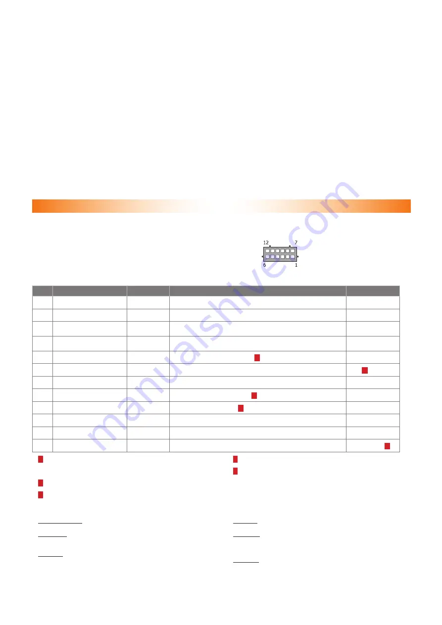
Immobilizer Inputs / Outputs functionalities are described in the Im-
mobilizer port description Table. Connection pin numeration is indicated
on fig. 1. Aside from outputs with set functions Immobilizer is equipped
with two programmable outputs each of which can be assigned with
one of 20 functions (see CAN bus adapter features table). These
outputs are set for controlling an accessory hood lock. Output con-
figuration is carried out via programming (see Immobilizer hardware
functions programming (Menu 1)).
Рис. 1.
Port connector pins
enumeration from wir-
ing viewpoint
Table 1. Immobilizer port description
No.
Color
Type
Function
Current, mA
1
Brown/red
CAN
CAN-H vehicle data bus
–
2
White/black
- output
Engine locking
150
3
Gray/green
- output
Programmable negative output (Lock Impulse by default)
50
4
Gray/blue
- output
Programmable negative output (driver authentication by default)
50
5
Blue/red
+/– output
Alternate hazard lights control
1)
150
6
Black
power supply Ground
–
2)
7
Brown
CAN
CAN-L vehicle data bus
–
8
Pink/Green
+ input
Brake lights condition control
3)
1,5
9
Yellow/red
-
Communication channel
4)
–
10
Gray/yellow
+ input
Analog button/Positive button
–
11
Gray/black
- input
Reference ground/Negative button
–
12
Red
power supply
+12 В
1200(3,5)
5)
1)
– Is an output with convertible electrical polarity. Polarity is set automati-
cally upon unit interfacing with the vehicle. This output is used for al-
ternate hazard lights control in vehicles that do not support CAN bus
control.
2)
– Useful current of output No. 6 depends on connected load of the nega-
tive outputs.
3)
– Input No. 8 is to be connected only in vehicles where CAN bus does
not contain data on brake pedal position (see Integrator files).
4)
– Upon Immobilizer installation it is necessary to check the connection
in between the central unit and the relay.
5)
– Maximum useful current rate in transfer (impulse) and idle modes
is indicated. It may vary depending on demand in output No. 5.
Outputs No. 2, 3, 4 are protected from short circuit, inductive erup-
tions, overheating and maximum demand surpassing.
Immobilizer pin connectors’ description
Pins No. 1 and 7. “CAN-H and CAN-L vehicle data bus” are connected
to vehicle CAN bus (see “Integrator files”).
Pin No. 2. “Engine lock” is connected to one of relay coil con-
tacts, which is used for engine operation or ignition lock. The output
can be set for controlling a normally-open or normally-closed relay
Pin No. 3. Programmable negative output (“Lock Impulse” by default).
Pin No. 4. Programmable negative output (“Vehicle owner authentica-
tion” by default).
Pin No. 5. “Alternate hazard light control” is used for hazard light
controlling on vehicles where CAN bus control is not available. Please
see Integrator files software product for information on vehicle-specific
connection features.
Pin No. 6. “Ground” is connected to vehicle body in one of the loca-
tions determined by vehicle manufacturer for original equipment ground
connection


