10
TEC-61231-23 Technical Manualе
PRIZRAK
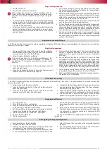
Description of pins in the Alarm main port
Pins #1, 10, 11.
Used only for additional (optional) modules
connected via TP-BUS (such as HCU-230 hood module, ESM-250
remotestart module, etc.).
Pin #2.
Heater control (Webasto, Eberspacher)
Pins #3, 12.
CAN2 vehicle data bus. Connected in particular cases
(please see the Integrator files).
Pins #4, 13.
CAN-L, CAN-H vehicle data buses. Connected to the
vehicle CAN bus (please see the Integrator files).
Pin #5.
Brake lights state. Used if the vehicle CAN bus does not
contain brake pedal position data (please see the Integrator files). In
such cases Pin
#5 is connected to the output of brake pedal terminal
switch.
Pin #6.
Engine lock. Connected to one of the relay coil contacts,
which is used to lock or startup the engine.
Pin #7.
Reference ground/Negative button. Subject to selected type
of a control button, one of the following functions is used:
•
Reference ground: when an analog control button is selected,
pin is connected to the appropriate wire of the vehicle (please
see the Integrator files)
•
Negative button: is connected to the negative (controlled by
making contact with the ground) button. It is used when there
are no original buttons recognized by the Alarm.
If the vehicle has original buttons operated via CAN bus and
recognized by the Alarm, this input can be vacant.
Pin #8. Data.
Connects to positive terminal of switched or non-
switched circuit. +12 V signal has to be present when the engine is
running. This connection is used to connect lock relay and the main
unit
Do not connect Data output to the cigarette lighter circuit.
Pin #9.
Ground. Connected to the vehicle body via connection point
designated by the vehicle’s manufacturer for ground connections with
factory equipment.
Pin #14.
Hood position state. Used only when the vehicle CAN bus
lacks information about hood position.
Pin #15.
(+/-) output. Alternative hazard lights control. Controls
hazard lights for the vehicles where CAN bus is not used. For more
details on how to use it in a specific vehicle please refer to the
Integrator.
Pin #16.
Analog button/Positive button.
Subject to selected type of a control button, one of the following
functions is used:
•
Analog button is connected to the relevant wire of the vehicle
at the steering wheel "helix" port (please see the Integrator
files)
•
Positive button is connected to the positive button (controlled
by +12V voltage). Used when original buttons are not
recognized by the Alarm.
If there are available original CAN buttons, and they are recognized
by the Alarm, this input can be left unused.
Pin #17.
Siren control/Horn control. Appropriate algorithm is set
when the Alarm is installed (see Programming the Alarm hardware
features).
Pin #18.
Power supply of the Alarm. Connected via 3A fuse to one of
the non-sw12 V circuits.
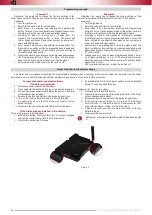
pLine-221 description and installation guidelines
Table 5. Relay outputs description
Color
Type
Note
Current
Red
Communication and power
+12 V
1
А/10 mА
*
Black
Power source
"
Ground
"
—
Yellow
Common contact
Lock output
10
А
Yellow/Red
Normally closed contact
Lock output
10
А
Yellow/Black (Yellow/White)
Normally open contact
Lock output
10
А
**
*
While transmitting data (pulses) up to 1 A. When receiving data up to 10 mA
**
Limited by cross section of the wire.
"
Communication and power
"
has to be connected to the positive
switched circuit of the vehicle. This circuit has to be enabled if the
Ignition is enabled (for example: ignition, injectors, ignition coils).
You may lock any circuit in the vehicle.
After installation it is recommecned to check link between relay
and Alarm.
Relay has a built-in accelerometer for vehicles that have no
information about speed in the CANbus, and enables extra features
for vehicles that have information about speed present in the CANbus:
•
Lock the engine even if there is no speed information in the
CAN bus
•
Accelerometer allows starting the engine and locking it if the
vehicle began movement.
It is not recommended to install the relay in places that vibrate
heavily during engine starting or launching. This can prevent movement
detecton due to excessive noise passed to accelerometer.
Factory default sensitivity settings mean that there are almost no
vibrations transfered from the engine.
After installing the alarm it is recommended to check sensitivity
settings and adjust them if required.
•
You may install only one pLine-221 relay in the vehicle.
•
Relay works as normally locked relay.
•
If same circuit that is used for connection with the alarm is locked,
"
Communication and power
"
has to be connected higher than
lock point
CAN bus parameters indication
Geature shown following parameters:
•
Hood, trunk, doors (each door individually)
•
Ignition switch state (key presence, АСС, IGN, Start)
•
Engine is running
•
Gearbox state (for automatic – P, R, N, D; for manual – R)
•
Parking brake
•
Stop-signal
•
Security
•
Factory security system alert
•
Central lock state
•
Sensors ignore
•
Engine RPM
•
Engine temperature
Feature allow quickly check vehicle state and adjust connection
if required. Buit-ib LED is used for indication (check
"
Connection
scheme
"
). LED lights up if any parameter is selected and stays for 5
seconds or until other parameter is chosen.
"
Engine RPM
"
and
"
Engine temperature
"
will be indicated if no
other parameters are chosen:
"
Engine RPM
"
— LED flashes with frequency proportional to the RPM:
1 flash per second equals 500 RPM of the engine.
"Engine temperature"
— LED flashes 1 time every time new data
received (with ignition or or the engine running).
Description of pins in the Alarm main port
Pin #2.
Heater control (Webasto, Eberspacher)
Pins #3, 12.
CAN2 vehicle data bus. Connected in particular cases
(please see the Integrator files).
Pins #4, 13.
CAN-L, CAN-H vehicle data buses. Connected to the
vehicle CAN bus (please see the Integrator files).
Pin #5.
Brake lights state. Used if the vehicle CAN bus does not
contain brake pedal position data (please see the Integrator files). In
such cases Pin
#5 is connected to the output of brake pedal terminal
switch.
Pin #6.
Engine lock. Connected to one of the relay coil contacts,
which is used to lock or startup the engine.
Pin #7.
Reference ground/Negative button. Subject to selected type
of a control button, one of the following functions is used:
•
Reference ground: when an analog control button is selected,
pin is connected to the appropriate wire of the vehicle (please
see the Integrator files)
•
Negative button: is connected to the negative (controlled by
making contact with the ground) button. It is used when there
are no original buttons recognized by the Alarm.
If the vehicle has original buttons operated via CAN bus and
recognized by the Alarm, this input can be vacant.
Pin #8. Data.
Connects to positive terminal of switched or non-
switched circuit. +12 V signal has to be present when the engine is
running. This connection is used to connect lock relay and the main
unit
Do not connect Data output to the cigarette lighter circuit.
Pin #9.
Ground. Connected to the vehicle body via connection point
designated by the vehicle’s manufacturer for ground connections with
factory equipment.
Pin #11.
Used only for additional (optional) modules connected
via TP-BUS (such as HCU-230 hood module, ESM-250 remotestart
module, etc.).
Pin #14.
Hood position state. Used only when the vehicle CAN bus
lacks information about hood position.
Pin #15.
(+/-) output. Alternative hazard lights control. Controls
hazard lights for the vehicles where CAN bus is not used. For more
details on how to use it in a specific vehicle please refer to the
Integrator.
Pin #16.
Analog button/Positive button.
Subject to selected type of a control button, one of the following
functions is used:
•
Analog button is connected to the relevant wire of the vehicle
at the steering wheel "helix" port (please see the Integrator
files)
•
Positive button is connected to the positive button (controlled
by +12V voltage). Used when original buttons are not
recognized by the Alarm.
If there are available original CAN buttons, and they are recognized
by the Alarm, this input can be left unused.
Pin #17.
Siren control/Horn control. Appropriate algorithm is set
when the Alarm is installed (see Programming the Alarm hardware
features).
Pin #18.
Power supply of the Alarm. Connected via 3A fuse to one of
the non-sw12 V circuits.
Description of pins in the Alarm main port
Pin #1.
For TEC-810/830.
Used only for additional (optional)
modules connected via TP-BUS (such as HCU-230 hood module, ESM-
250 remotestart module, etc.). Power for additional devices
For TEC-810/830 with thermal sensor
Used as ground for
engine temperature sensor
Pin #2.
Heater control (Webasto, Eberspacher)
Pins #3, 12.
CAN2 vehicle data bus. Connected in particular cases
(please see the Integrator files).
Pins #4, 13.
CAN-L, CAN-H vehicle data buses. Connected to the
vehicle CAN bus (please see the Integrator files).
Pin #5.
Brake lights state. Used if the vehicle CAN bus does not
contain brake pedal position data (please see the Integrator files). In
such cases Pin
#5 is connected to the output of brake pedal terminal
switch.
Pin #6.
Engine lock. Connected to one of the relay coil contacts,
which is used to lock or startup the engine.
Pin #7.
Reference ground/Negative button. Subject to selected type
of a control button, one of the following functions is used:
•
Reference ground: when an analog control button is selected,
pin is connected to the appropriate wire of the vehicle (please
see the Integrator files)
•
Negative button: is connected to the negative (controlled by
making contact with the ground) button. It is used when there
are no original buttons recognized by the Alarm.
If the vehicle has original buttons operated via CAN bus and
recognized by the Alarm, this input can be vacant.
Pin #8. Data.
Connects to positive terminal of switched or non-
switched circuit. +12 V signal has to be present when the engine is
running. This connection is used to connect lock relay and the main
unit
Do not connect Data output to the cigarette lighter circuit.
Pin #9.
Ground. Connected to the vehicle body via connection point
designated by the vehicle’s manufacturer for ground connections with
factory equipment.
Pin #10.
For TEC-810/830.
Used only for additional (optional)
modules connected via TP-BUS (such as HCU-230 hood module, ESM-
250 remotestart module, etc.). Power for additional devices
For TEC-810/830 with thermal sensor
Used as power for
engine temperature sensor
Pin #11.
Used only for additional (optional) modules connected
via TP-BUS (such as HCU-230 hood module, ESM-250 remotestart
module, etc.).
Pin #14.
Hood position state. Used only when the vehicle CAN bus
lacks information about hood position.
Pin #15.
(+/-) output. Alternative hazard lights control. Controls
hazard lights for the vehicles where CAN bus is not used. For more
details on how to use it in a specific vehicle please refer to the
Integrator.
Pin #16.
Analog button/Positive button.
Subject to selected type of a control button, one of the following
functions is used:
•
Analog button is connected to the relevant wire of the vehicle at
the steering wheel "helix" port (please see the Integrator files)
•
Positive button is connected to the positive button (controlled
by +12V voltage). Used when original buttons are not
recognized by the Alarm.
If there are available original CAN buttons, and they are recognized
by the Alarm, this input can be left unused.
Pin #17.
Siren control/Horn control. Appropriate algorithm is set
when the Alarm is installed (see Programming the Alarm hardware
features).
Pin #18.
Power supply of the Alarm. Connected via 3A fuse to one
of the non-sw12 V circuits.


