13
TEC-61231-23 Technical Manualе
PRIZRAK
22
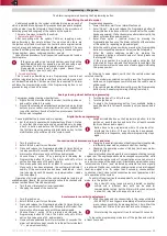
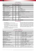
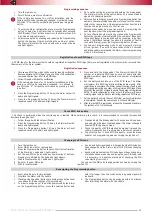
Fuel tank volume
1-30
1
Used to convert fuel level from percent to liters.
1 – not defined. Fuel is measured in percent
2 - 10 liters..30-150 liters. Step is five liters
23
Alert delay if perimeter
was breached
1-5
1
1 - disabled; 2 - 0.5s; 3 - 1.0-s; 4 - 2.0s; 5 - 3.0s;
24
Engine lock via CAN
1-2
2
1 - enabled; 2 - disabled. If feature is enabled and
supported by the vehicle(check Integrator) - engine can
be locked via CAN bus (without additional connections)
25
Perimeter control pause(30s)
1-2
2
1 - on; 2 - off;
26
Beach mode
–
-
–
27
Immobilizer bypass unit
1-2
-
Set automatically. 1 - Fortin; 2 - iDatalink;
Option
#13.
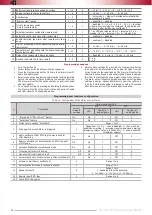
"Parking system operation algorithm":
•
"Activation by reverse gear". Front and rear parking sensors are
switched on when gearbox is in R position or by using a control
button. They are switched off when the speed exceeds 15 km/h
or by using the parking system control button
•
"Activation by speed". Front parking sensors are switched on if
the vehicle speed is under 15 km/h. Rear parking sensors are
switched on if the vehicle moves backwards with a speed under 15 km/h.
In this mode all parking sensors can be disabled by using a control
button until the next ignition sequence or command from a control
button
•
"Activation by reverse gear with a shutdown override". Here
algorithm is similar to "Activation by reverse gear". However, when
parking sensors are disabled by using a control button, they will not
be activated when gearbox is in R position up to the next ignition or
command from a control button.
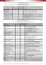
Table 8. Configuration of programmable configuration of inputs/outputs
#
Connector
Function
Setting range
Factory
default settings
1
X1
18-pin
(+/–) output
#15
(18-pin port)
1-41/Alternate hazard lights control
Hazard lights alternate control
2
Polarity of output
#15
1-2
Negative polarity
3
X2
8-pin
(–) output
#5
(8-pin port)
1-41
17
4
(–) output
#6
(8-pin port)
1-41
18
5
(–) output
#7
(8-pin port)
1-41
25/alter. Central Lock
6
(–) output
#8
(8-pin port)
1-41
4/alter. Central Lock
7
(–) input
#1
(8-pin port)
1-24
12
8
(+) input
#2
(8-pin port)
1-24
7
9
X1
18-pin
(+) input
#5
(18-pin port)
1-24
1
10
(-) input
#7
(18-pin port)
1-24
–
11
(-) input
#14
(18-pin port)
1-24
2
12
(+) input
#16
(18-pin port)
1-24
–
Options 1, 3-6.
Designed to customize the Alarm outputs by
assigning a function to a specific output (see "Programmable output
functions" table).
Option 2.
Defines the polarity of the Alarm output
#
17.
The polarity can be defined only if this output is assigned one of
the functions (see "Programmable output functions").
Option 5
Arming pulse or lock Central Lock/lock/unlock Central
Lock
Option 6
Identity verification pulse or unlock Central Lock
Options 7, 12
To be able to program this pin “Digital buttons”
option has to be chosen
Options 7-14.
Designed to customize the Alarm inputs by assigning
a function to a specific input (see "Programmable input functions"
table).


