background image

5235 

TECSource

 User’s Manual · Page 21 


To manually adjust the PID, start by changing the I and D values to zero, and 

adjust the P value so that it reaches the set point as quickly as possible without 
overshooting the set point an unacceptable amount. Gradually increase the I 
value until the set point is achieved without oscillation. In many systems, the D 
term is not needed and may be left at zero. 
 
For additional information on PID loop tuning, consult online resources such as 

Wikipedia (http://en.wikipedia.org/wiki/PID_controller) or search for terms such 
as “Ziegler-Nichols method”, or “PID Loop”. 
 

Compensating for Cable Resistance 


Because the high currents the 

TECSource

 can drive through the Peltier, the 

voltage loss through the cable and connectors of the system can significantly 
affect the TEC voltage measurement. In most cases, accurate voltage 

measurements are not needed, and the default compensation of the instrument 
is sufficient. To improve the compensation, the 

Cable R

 setting in the menu 

allows you to specify the cable resistance, which is then used to dynamically 
subtract the voltage drop by simply using the formula V = IR to calculate the 
voltage loss, where I is the TEC ITE current, and R is the 

Cable R

 setting. This 

value is then removed from the voltage measurement to display an accurate 
TEC voltage measurement.  
 
The safest method of calculating cable resistance is to short the ITE+ and ITE– 
connections, making sure whatever you are using to short the terminals is not 

itself adding resistance to the circuit. Use short, heavy gauge wires, preferably 
soldered onto the terminals to minimize any resistance the short might add. 
Place the short as close to the Peltier as is reasonable. A simple approach is to 
unplug the cable from the mount and place a shorting plug on the mount end of 
the cable, which is easily made from a male DB15 connector and a soldering 

iron to solder the ITE+ and ITE– pins together. Make sure the Peltier is 
disconnected to protect it from current overloading during the test. 
 
Change the instrument to ITE mode and set the current to 5A. Depending on 
your setup, you may first need to change the Mount to User Defined and adjust 
the limit to 5A. Turn on the output and after the voltage has stabilize, make a 

note of it and turn the output off. Enter the measured voltage into the following 
equation to calculate 

Cable R


Cable R = Voltage / 5 


Enter the resulting values into the 

Cable R

 menu entry and return the instrument 

to its original configuration. Typical values for 

Cable R

 are 0.008 to 0.040, but 

depend on your actual configuration. 


Summary of Contents for Arroyo 5235

Page 1: ......

Page 2: ...rs are displayed in clear English no cryptic numbers or LEDs to decode The TECSource offers all the features you would expect from a modern temperature controller including 0 004 C temperature stabili...

Page 3: ...conditions that could result in damage to the instrument other equipment or your device Notes noted by the NOTES heading are not safety related and are intended simply to point out important informati...

Page 4: ...able parts inside All service and repair work shall be done by Arroyo Instruments or personnel authorized by Arroyo Instruments Modifications done by non authorized personnel will void the warranty Pl...

Page 5: ...he TECSource is being connected to a LaserMount no changes need to be made as this is the thermistor used in the mount However if you are using manufacturer s thermistor or a different BetaTHERM therm...

Page 6: ...quickly jumping up and down the Gain will typically need to be reduced If the temperature is slowly moving up and down try a higher Gain You may need to experiment with several gain settings to find t...

Page 7: ...as been made connect the AC power cord to the unit Turn the power switch located on the rear input power connector into the on position The unit will display the current firmware revision go through a...

Page 8: ...and therefore inside the rack housing be sure that the internal rack ambient temperature which will typically be several degrees higher than room ambient does not exceed the unit s operating temperat...

Page 9: ...n enter button when making changes in the menu When in the main screen pressing the knob will change from Normal to Large display mode There are four LEDs a green power LED that is lit whenever the AC...

Page 10: ...ensor value is known or when the sensor to temperature conversion values are not available for your sensor Main Display Screen On the main display you will find the set point and two or three measurem...

Page 11: ...re controllers Using Limits The TECSource supports three different types of limits temperature sensor and current There is both a temperature high and temperature low limit and if the actual temperatu...

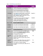
Page 12: ...ress the knob to enter the sub menu when its name is displayed Below is a complete list of available settings Menu Description Factory Default Root Menu Main Menu Mode This set the operating mode T Mo...

Page 13: ...ses above this value the output will be turned off Temperature limits not monitored in R Mode or Ite Mode Limit monitoring can also be disabled in software see TEC ENAB OUTOFF command 125 C R Low Lim...

Page 14: ...ving the voltage loss of the cable 0 0080 Sensor Coeffs Sensor Coefficients Menu ThermA The A term in the Steinhart Hart equation 1 12924E 03 ThermB The B term in the Steinhart Hart equation 2 34108E...

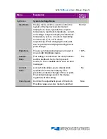
Page 15: ...t point the set point will be displayed during the set point change Normal Brightness The vacuum florescent display can be set to one of eight brightness levels 100 Audible Beep This setting controls...

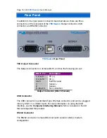
Page 16: ...e following pin out DB 15 Pin Description 1 2 9 TE 3 4 10 TE 5 6 Earth Ground 7 Sensor 8 Sensor 11 thru 15 No connection Output Connector DB 15 Female USB Connector The USB connector is a standard Typ...

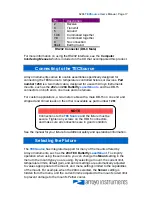
Page 17: ...d and tinned leads on the other is available as part number 1261 See the manual for your fixture for additional safety and operational information Selecting the Fixture The TECSource has integrated su...

Page 18: ...terfacing Manual which is included on the CD that accompanied this product Installing the USB Drivers Using the TECSource via USB is just as simple as using the serial port In fact once you have insta...

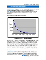
Page 19: ...typical control range 0 C to 40 C typical 10K thermistors offer good sensitivity to changes in temperature and this is the range in which most 10K thermistors are typically used 10K thermistors can be...

Page 20: ...ible and the TECSource must be configured to not attempt to cool the output or a run away condition will occur when the cooling current actually causes additional heating If your application requires...

Page 21: ...E current and R is the Cable R setting This value is then removed from the voltage measurement to display an accurate TEC voltage measurement The safest method of calculating cable resistance is to sh...

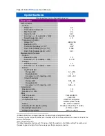
Page 22: ...ccuracy reading 0 05 50 100 A Thermistor Range k 0 05 45 Resolution 1 Accuracy reading 0 05 5 Current Limit Resolution mA 10 Accuracy mA 50 Other TEC Connector Female DB 15 Display Type 2x20 VFD Compu...

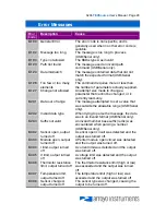
Page 23: ...he allowable range USB Serial only E 202 Invalid data type When trying to parse the message the data was in an invalid format USB Serial only E 204 Suffix not valid An invalid number base suffix radix...

Page 24: ...for more than 20 seconds E 433 Not a TEC The TEC CHAN command attempted to select a non TEC channel E 434 Ite limit exceeds cable rating The cable plugged into the unit is not rated to carry the curre...

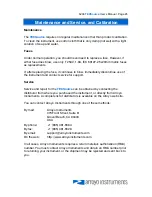
Page 25: ...vice for support Service Service and repair for the TECSource can be obtained by contacting the distributor from where you purchased the instrument or directly from Arroyo Instruments A complete list...

Page 26: ...Page 26 5235 TECSource User s Manual Notes...

Page 27: ...5235 TECSource User s Manual Page 27 Notes...

Page 28: ...Page 28 5235 TECSource User s Manual Copyright 2008 Arroyo Instruments All Rights Reserved P N 530 1012 Rev A...

Reviews: