background image

(i)

Safety Summary

EO1-33006

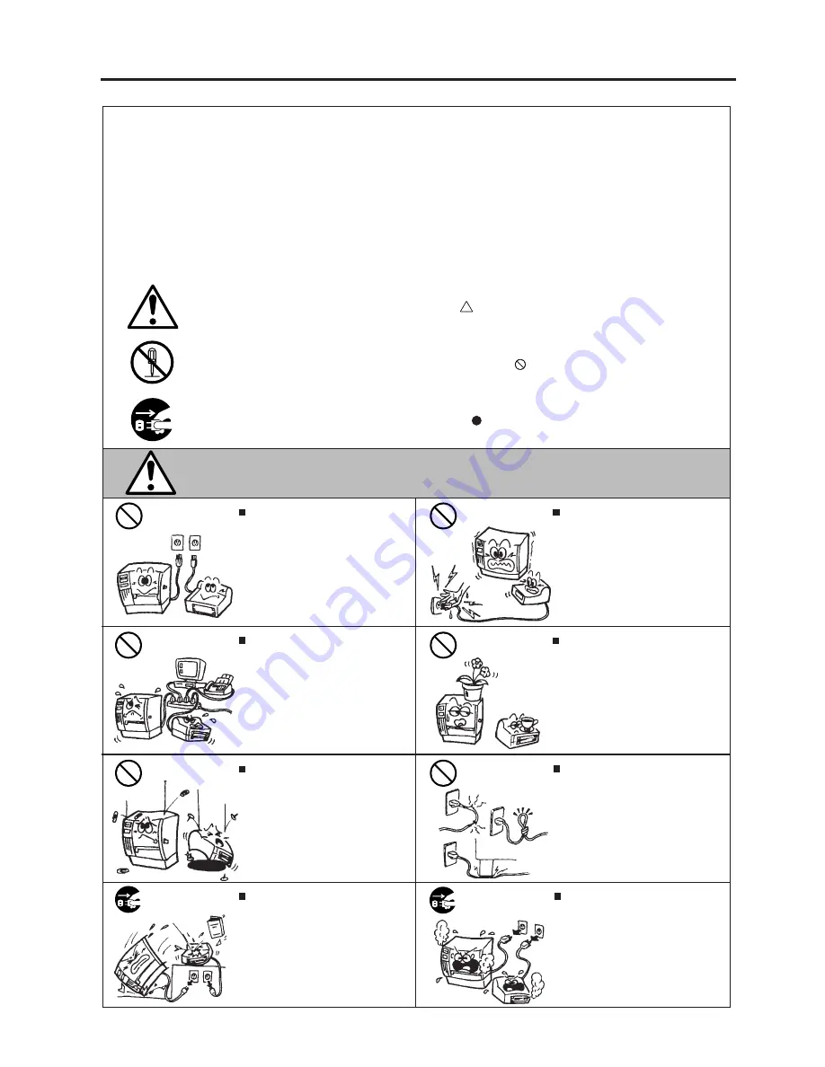
   Continued use of the machines in an
abnormal condition such as when the
machines are producing smoke or
strange smells may cause fire or elec-
tric shock
.  In these cases, immedi-
ately turn off the power switches and
disconnect the power cord plugs from
the outlet.  Then, contact your author-
ized TOSHIBA TEC representative for
assistance.

Safety Summary

Personal safety in handling or maintaining the equipment is extremely important.  Warnings and Cautions
necessary for safe handling are included in this manual.  All warnings and cautions contained in this
manual should be read and understood before handling or maintaining the equipment.
Do not attempt to effect repairs or modifications to this equipment.  If a fault occurs that cannot be rectified
using the procedures described in this manual, turn off the power, unplug the machine, then contact your
authorized TOSHIBA TEC representative for assistance.

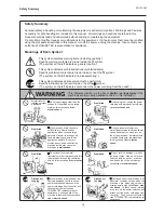
Meanings of Each Symbol

This symbol indicates warning items (including cautions).
Specific warning contents are drawn inside the     symbol.
(The symbol on the left indicates a general caution.)

This symbol indicates prohibited actions (prohibited items).
Specific prohibited contents are drawn inside or near the     symbol.
(The symbol on the left indicates “no disassembling”.)

This symbol indicates actions which must be performed.
Specific instructions are drawn inside or near the    symbol.
(The symbol on the left indicates “disconnect the power cord plug from the outlet”.)

   Do not use voltages other than the
voltage (AC) specified on the rating
plate, as this may cause fire or
electric shock.

Any other than the
specified AC voltage
is prohibited.

WARNING

This indicates that there is the risk of death or serious injury if the
machines are improperly handled contrary to this indication.

Prohibited

   Do not plug in or unplug the power
cord plug with wet hands as this may
cause electric shock.

   Do not place metal objects or
water-filled containers such as flower
vases, flower pots or mugs, etc. on
top of the machines.  If metal objects
or spilled liquid enter the machines,
this may cause fire or electric
shock
.

   If the machines share the same
outlet with any other electrical
appliances which consume large
amounts of power, the voltage will
fluctuate widely each time these
appliances operate.  Be sure to
provide an exclusive outlet for the
machine as this may cause the
machines to malfunction.

   Do not insert or drop metal,
flammable or other foreign objects into
the machines through the ventilation
slits, as this may cause fire or electric
shock
.

Prohibited

Prohibited

Prohibited

   Do not scratch, damage or modify
the power cords.  Also, do not place
heavy objects on, pull on, or exces-
sively bend the cords, as this may
cause fire or electrical shock.

Prohibited

Disconnect
the plug.

   If the machines are dropped or their
cabinets damaged, first turn off the
power switches and disconnect the
power cord plugs from the outlet, and
then contact your authorized
TOSHIBA TEC representative for
assistance.  Continued use of the
machine in that condition may cause
fire or electric shock.

Disconnect
the plug.

Summary of Contents for B-450-QQ Series

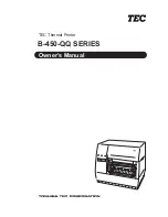
Page 1: ...TEC Thermal Printer B 450 QQ SERIES Owner s Manual...

Page 2: ...d used in accordance with the instruction manual may cause harmful interference to radio communications Operations of this equipment in a residential area is likely to cause harmful interference in wh...

Page 3: ...e power cord plug from the outlet Do not use voltages other than the voltage AC specified on the rating plate as this may cause fire or electric shock Any other than the specified AC voltage is prohib...

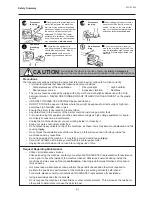
Page 4: ...ribbons DO NOT STORE the paper or ribbons where they might be exposed to direct sunlight high tem peratures high humidity dust or gas Ensure the printer is operated on a level surface Any data stored...

Page 5: ...1 6 1 INSTALLING THE SUPPLY HOLDER UNIT 6 1 6 2 CONNECTING THE POWER CORD AND CABLES 6 1 7 LOADING THE RIBBON 7 1 8 LOADING THE PAPER 8 1 9 THRESHOLD SETTING 9 1 10 CARE HANDLING OF THE PAPER AND RIB...

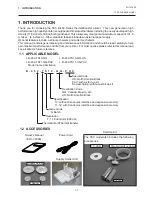
Page 6: ...erformance and life from your printer For most queries please refer to this manual and keep it safe for future reference 1 1 APPLICABLE MODEL B 452 TS10 QQ B 452 TS10 QQ US B 452 TS11 QQ PAC B 452 TS1...

Page 7: ...mm sec 4 inch sec Maximum print width 105 7 mm 4 16 inches Dispensing modes Batch Continuous Strip Option and Cut modes Option Bothcutandstripmodesareavailableonlywhentheirrespectivemodules are fitte...

Page 8: ...Width 60 mm 110 mm Length 300 m Outer diameter 65 mm max Use This cutter module uses a rotary cutter It cuts backing paper of labels and tag paper automatically in stop and cut mode This strip module...

Page 9: ...nication error occurs when the paper ribbon ends or the printer is not operating cor rectly FEED Key Feeds paper PAUSE Key Pauses printing Resets the printer when paused or when an error occurs Fig 3...

Page 10: ...combination of DIPSWs 6 and 7 DIP SW Fig 4 1 WARNING Turn the POWER OFF before changing the DIP switches DIP SW No 1 2 3 4 5 6 7 8 ON OFF 1 OFF ON OFF ON 2 OFF OFF ON ON OFF ON OFF ON OFF ON 6 OFF ON...

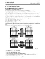
Page 11: ...ower line conduits RS 232C Cable description The serial data cable used to connect the printer to the host computer should be one of the following two types NOTE Use an RS 232C cable with imperial inc...

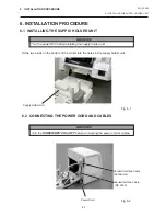
Page 12: ...Interface Cable RS 232C WARNING Turn the POWER SWITCH to OFF before connecting the power cord or cables Fit the two studs on the bottom of the printer into the holes in the supply holder unit 6 2 CON...

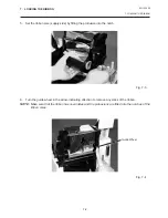
Page 13: ...the power off and open the top cover 2 Move the head release lever toward the front of the printer and raise the print head block Fig 7 2 Fig 7 1 Print Head Block Head Release Lever Top Cover 3 Fit t...

Page 14: ...ly side by fitting the protrusion into the notch 6 Turn the guide wheel in the arrow indicating direction to remove any slack of the ribbon NOTE Make sure that the ribbon has no wrinkles and the protr...

Page 15: ...mm When using a paper roll of 38 mm 40 mm or 42 mm remove the spacers from the supply holders using the following procedure 1 Push both hooks of the spacer to remove it from the supply holder Keep the...

Page 16: ...SupplyHolderGuide Lock Lever 4 Push both sides of the supply holder guides against the paper roll then lock them with the lock lever NOTE Make sure that the supply holders rotate slightly 5 Pass the...

Page 17: ...7 Supply Holder Paper Guide Paper Platen A B A B Cutter type Whereacutterisfittedloadthepaperasstandardandfeeditthroughthecuttermodule NOTES 1 When using the cutter be sure to cut the backing paper b...

Page 18: ...m the top edge of the label roll 2 First push the strip lever toward the printer to release the hook and then pull the strip lever 3 Pass the backing paper between the strip roller and the strip guide...

Page 19: ...E key The paper will feed through the printer until the PAUSE key is released Release the PAUSE key after more than 1 5 labels have been fed Threshold setting is completed by this operation 6 Turn the...

Page 20: ...l paper used for direct thermal printing must not have the specifications which exceed Na 800 ppm K 250 ppm and CL 500 ppm Some ink used on pre printed labels may contain ingredients which shorten the...

Page 21: ...horized TOSHIBA TEC service representative Print Head Thermal Element WARNING 1 Be sure to disconnect the power cord prior to performing any maintenance 2 DO NOT POUR WATER directly onto the printer F...

Page 22: ...Holder Roller Recessedportionofthebase Supply Holder Base Platen Black mark Feed gap sensor 11 2 COVERS The covers should be cleaned by wiping with a dry cloth or a cloth slightly dampened with a mil...

Page 23: ...ust or foreign substances 7 Paper jams in the cutter unit can be caused by wear or residual glue from label stock on the cutter Do not use unspecified paper in the cutter If frequent jams occur in the...

Page 24: ...trip Unit 1 First push the strip lever toward the printer to release the hook and then pull the strip lever 2 Remove the jammed paper if any 3 Clean the strip guide rollers A and B with a cloth moiste...

Page 25: ...zed Service represen tative Problem 1 The paper is not fitted correctly 2 The paper path is jammed and does not feed smoothly 3 The installed paper type does not match the selected sensor 4 The instal...

Page 26: ...er and ribbon are loaded correctly 2 Check that print head is set correctly 3 Check the cabling between the printer and the host Dirty print head Clean the print head Call your Authorized Service repr...

Page 27: ...13 1 EO1 33006 APPENDIX APPENDIX APPENDIX ASCII Code Chart Font Sample Barcode Sample...

Page 28: ...face board 2 2 Keyboard module 2 2 Strip mechanism 1 1 Strip module 2 2 P Paper 2 2 10 1 Paper jam 12 1 Power consumption 2 1 Power cord 1 1 6 1 Power switch 3 1 Print head 1 1 2 1 11 1 Print head cle...

Page 29: ......

Page 30: ...PRINTED IN JAPAN EO1 33006 E...

Reviews: