2-2
2. MAJOR UNIT REPLACEMENT
EM18-33011
(Revision Date: Oct. 14 '94)
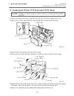
2.1 Replacing the PS Unit, I/F PC Board and CPU PC Board
2.1 Replacing the PS Unit, I/F PC Board and CPU PC Board
CAUTION: Replace only with same type and ratings of fuse for continued protection against
risk of fire.
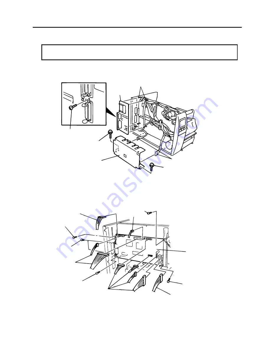
1) Remove the three FL-4x6 screws and disconnect the two connectors to detach the PS unit.
2) Remove the FL-3x5 screw and the four locking supports to remove the I/F PC board.
3) Disconnect the 9 connectors from the CPU PC board.
4) Remove the six screws (SM-3x6B, SM-3x6C) to detach the CPU PC board from the printer.
5) Replace the PS unit, I/F PC board and CPU PC board. Insert the connectors correctly and install in
the reverse order of removal above. Do not mount the left side cover and top cover.
6) Make sure to adjust the various voltages after replacing the CPU PC board.
Fig. 2-2
Fig. 2-3
Locking Support
Connector
Screw (FL-4x6)
PS Unit
Screw (FL-4x6)
Screw (FL-3x5)
I/F PC Board
Screw (SM-3x6B)
CPU PC Board
Screw (SM-3x6B)
Connector
Connector
Connector
Screw (SM-3x6B)
Screw (SM-3x6C)
Connector
Screw (SM-3x6B)
Connector

