3-7
EM18-33017
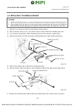
3. INSTALLATION PROCEDURE FOR OPTIONAL EQUIPMENT
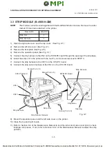
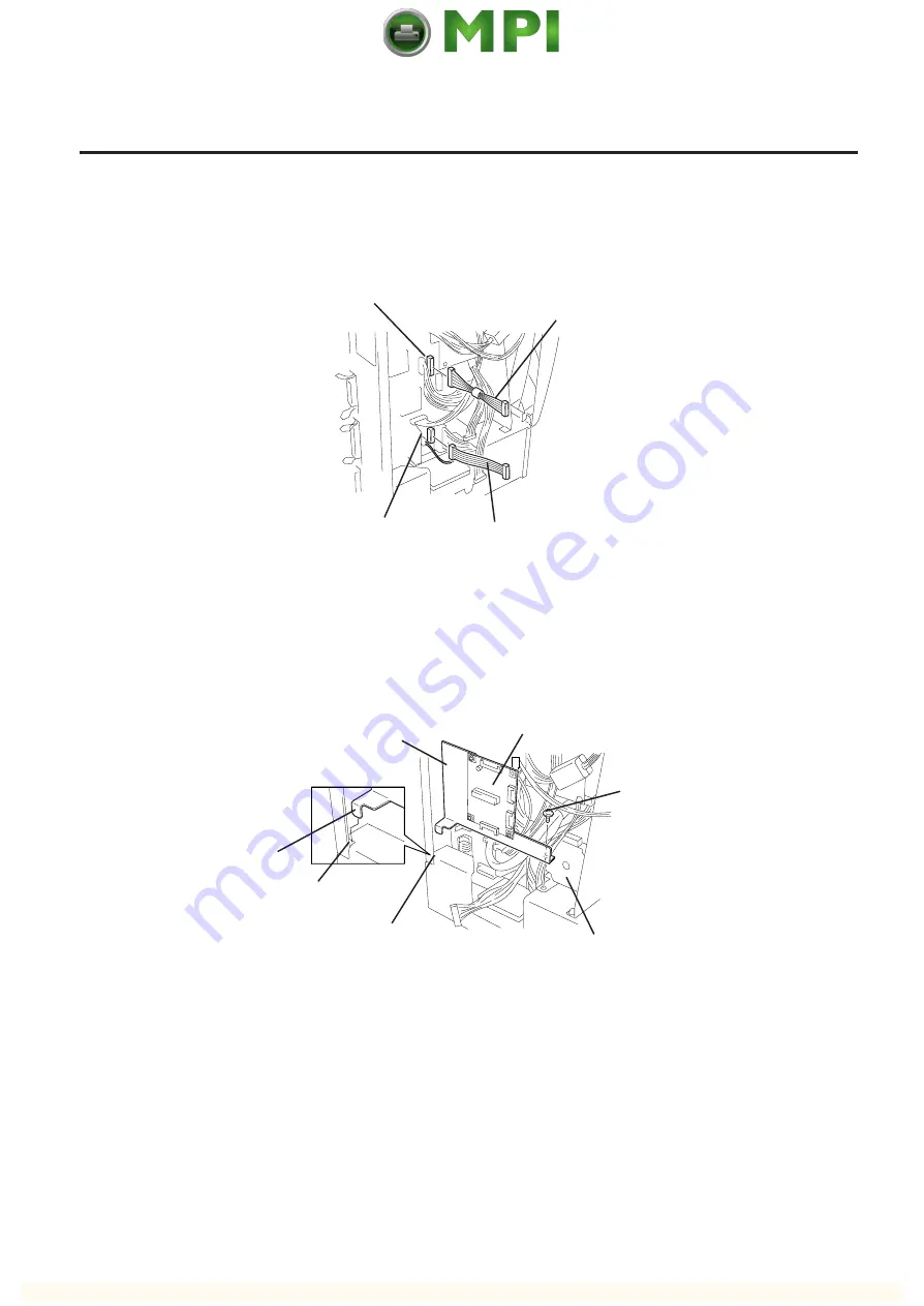
Harness S (Yellow)
Harness P (Black)
CN9
CN17
Stabilizer PC Board Ass’y
Guide Plate
Square Hole
Part B
Stepping Motor
Screw A
Guide Plate
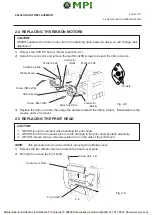
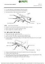
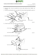
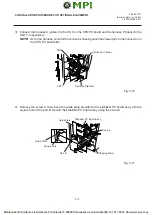
3) Connect the harness S (yellow) to the CN 9 on the CPU PC board and the harness P (black) to the
CN 17, respectively.
NOTE: As for the harness, connect the connector housing which has fewer pins to the connector on
the CPU PC board side.
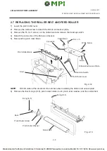
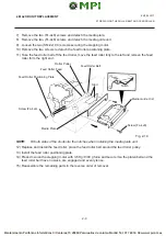
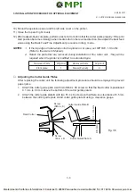
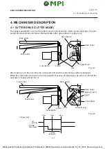
4) Remove the screw A, then insert the guide plate provided to the stabilizer PC board ass’y into the
square hole of the part B. Secure the stabilizer PC board ass’y using the screw A.
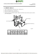
Fig. 3-10
Fig. 3-11
(Revision Date: Jul. 26 '99)
3.4 STABILIZER KIT


