


6-47
6. DIAG. TEST OPERATION
EO18-33007
6.3 PARAMETER SETTING MODE
NOTE:
The following operation cannot be performed unless the sensor type is changed by the issue
command or feed command.
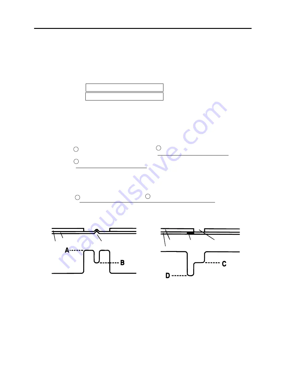
(1)
Using the sensor adjustment in Diag. mode, measure the sensor voltage at the following four
points.
Label:
Print area Backing paper
Tag paper: Print area Black mark
Example:
[ R E F L E C T I V E ] 2 . 8 V
[ T R A N S M I S S I V E ] 4 . 1 V
Min. voltage at the backing paper
2
Min. voltage at the backing paper
2
A
A
B
C
(Min. voltage at the print area) - (Min. voltage at the black mark)
2
(2.8V)
(1.5V)
(4.4V)
(0.7V)
Label gap
Black Mark
Label
Backing Paper
Perforation
Backing Paper
Label
D
(2)
Using the following formula, calculate the threshold from the measured voltage:
When using labels (transmissive sensor):
Threshold = (Max. voltage at the backing paper) - (Voltage at the print area) - 0.7V
e.g.) 2.0V = 4.2V - 1.5V - 0.7V
When using perforated labels (transmissive sensor):
Threshold = (Max. voltage at the backing paper) -
-
e.g.) 2.2V = 4.4V - (2.8V/2) - (1.6V/2)
When using labels with black marks (reflective sensor):
Threshold =
e.g.)
0.4V = (1.5V - 0.7V)/2
Summary of Contents for B-880 series
Page 3: ...TEC Thermal Printer B 870 880 QQ SERIES Owner s Manual ...
Page 35: ......
Page 36: ...PRINTED IN JAPAN EO1 33017 ...
Page 56: ......
Page 57: ......
Page 58: ...PRINTED IN JAPAN EO10 33008 ...
Page 146: ...6 59 6 DIAG TEST OPERATION EO18 33007 Fig 6 25 Bar code AUTO PRINT Fig 6 24 ...
Page 176: ......
Page 177: ......
Page 178: ...PRINTED IN JAPAN EO18 33007 ...
Page 179: ......
Page 180: ......


