background image

2. PRINTER SETUP 

ENGLISH VERSION EO1-33036 

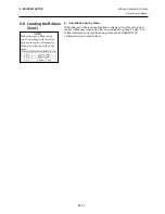
2.7 Loading the Media


E2- 7 


2.7  Loading the Media 

(Cont.) 


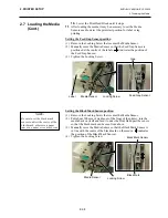
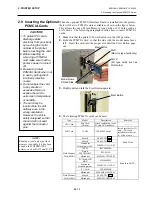
5.

  Put the media on the Supply Shaft. 

6.

  Pass the media around the Damper, then pull the media towards the 

front of the printer.  

7.

  Align the projection of the Supply Holder with the groove of the 

Supply Shaft, and push the Supply Holder against the media until the 
media is held firmly in place.  This will centre the media 
automatically. 
Then turn the Locking Ring clockwise to secure the Supply Holder.  


8.

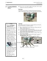
  Place the media between the Media Guides, adjust the Media Guides 

to the media width, and tighten the Locking Screw. 

9.

  Check that the media path through the printer is straight.  The media 

should be centred under the Print Head.  


NOTE: 

Do not over-tighten the Locking 
Ring of the Supply Holder. 

Supply Shaft 

Supply Holder 

Groove

Damper 

Locking Ring 

Projection 

Media 

Media Guide 

Supply Holder 

Media Guide 

Print Head 

Locking Screw 

Media 

Damper 

Media 

In case of a label rolled with
the print side facing inside. 

In case of a label rolled with 
the print side facing outside. 

Summary of Contents for B-SX4T Series

Page 1: ...X5T SERIES Document No EO0 33013AUM Original Jan 2003 Revised Feb 2003 User s Manual TABLE OF CONTENTS B SX5T OWNER S MANUAL EO1 33036 PRODUCT DESCRIPTION EO10 33013A MAINTENANCE MANUAL EO18 33012A B SX4T OWNER S MANUAL EO1 33034 ...

Page 2: ...ng or maintaining the equipment is extremely important Warnings and Cautions necessary for safe handling are included in this manual All warnings and cautions contained in this manual and written inside or outside of the printer should be read and understood before handling or maintaining the equipment Never modify the machine Except for the addition of options as specifically provided for in the ...

Page 3: ...TEC Thermal Printer B SX4T QQ QP Owner s Manual ...

Page 4: ...ss proprietors can participate voluntarily The targeted products are office equipment such as computers monitors printers facsimiles copiers scanners and multifunction devices Their standards and logos are uniform among participating nations ENERGY STAR is a U S registered mark This equipment has been tested and found to comply with the limits for a Class A digital device pursuant to Part 15 of th...

Page 5: ...r cord plug with wet hands as this may cause electric shock If the machines share the same outlet with any other electrical appliances that consume large amounts of power the voltage will fluctuate widely each time these appliances operate Be sure to provide an exclusive outlet for the machine as this may cause fire or electric shock Do not place metal objects or water filled containers such as fl...

Page 6: ...ures high humidity dust or gas Ensure the printer is operated on a level surface Any data stored in the memory of the printer could be lost during a printer fault Try to avoid using this equipment on the same power supply as high voltage equipment or equipment likely to cause mains interference Unplug the machine whenever you are working inside it or cleaning it Keep your work environment static f...

Page 7: ...e Power Cord E2 4 2 6 Turning the Printer ON OFF E2 5 2 6 1 Turning ON the Printer E2 5 2 6 2 Turning OFF the Printer E2 5 2 7 Loading the Media E2 6 2 8 Loading the Ribbon E2 11 2 9 Inserting the Optional PCMCIA Cards E2 12 2 10 Test Print E2 13 3 ON LINE MODE E3 1 3 1 Operation Panel E3 1 3 2 Operation E3 2 3 3 Reset E3 2 3 4 Dump Mode E3 3 4 MAINTENANCE E4 1 4 1 Cleaning E4 1 4 1 1 Print Head P...

Page 8: ...APPENDIX 3 INTERFACE EA3 1 APPENDIX 4 PRINT SAMPLES EA4 1 GLOSSARIES INDEX CAUTION 1 This manual may not be copied in whole or in part without prior written permission of TOSHIBA TEC 2 The contents of this manual may be changed without notification 3 Please refer to your local Authorised Service representative with regard to any queries you may have in this manual This is a Class A product In a do...

Page 9: ...moved from the centre to the left edge of the media When the optional interface board is installed Web functions such as remote maintenance and other advanced network features are available Superior hardware including the specially developed 8 dots mm 203 dots inch thermal print head which will allow very clear print at a printing speed of 76 2 mm sec 3 inches sec 152 4 mm sec 6 inches sec or 254 ...

Page 10: ...en unpacking the printer please make sure all the following accessories are supplied with the printer US Power Cord 1 pc P No FBCB0030203 QQ model only CD ROM 1 pc QQ P No 7FM00331000 QP P No 7FM00254000 EU Power Cord 1 pc P No EKA 0030001 QP model only Fan Filter 1 pc P No FMBB0036801 ...

Page 11: ...ing chapters Dimensions in mm inches LCD Message Display Operation Panel Power Switch OFF ON Media Outlet Top Cover Expansion I O Interface Connector Option Serial Interface Connector RS 232C Parallel Interface Connector Centronics Supply Window PCMCIA Card Slot Option USB Connector Option or LAN Connector Option AC Power Inlet 291 460 308 308 12 1 291 11 5 460 18 1 USB Connector Option or LAN Con...

Page 12: ...Interior Please see Section 3 1 for further information about the Operation Panel LCD Message Display ON LINE LED Green ERROR LED Red PAUSE key POWER LED Green FEED key RESTART key Ribbon Stopper Print Head Block Head Lever Ribbon Shaft Supply Holder Locking Ring Supply Shaft Print Head Platen ...

Page 13: ...ver open Be careful not to allow fingers or articles of clothing to get caught into any of the moving parts of the printer especially the optional cutter mechanism Make sure to turn off the printer power and to remove the power cord from the printer whenever working on the inside of the printer such as changing the ribbon or loading the media or when cleaning the printer For best results and longe...

Page 14: ...ark Sensor depending on the media being used Refer to Section 2 7 8 Load the ribbon Refer to Section 2 8 9 Turn the power ON Refer to Section 2 6 10 Perform a test print Refer to Section 2 10 11 Install the Printer Drivers Refer to the Printer Driver Manual When installing the printer it is important to ensure that the Fan Filter is attached before using the printer The Fan Filter consists of 2 pa...

Page 15: ...ard parallel connector and your host computer s parallel port LPT An Ethernet connection using the optional LAN board A USB cable connection between the printer s optional USB connector and your host computer s USB port Conforming to USB 1 1 The diagram below shows all the possible cable connections to the current version of the printer c Parallel Interface Connector Centronics d Serial Interface ...

Page 16: ...into a grounded outlet as shown in the figure below QQ Type QP Type CAUTION 1 Make sure that the printer Power Switch is turned to the OFF position before connecting the Power Cord to prevent possible electric shock or damage to the printer 2 Use only the Power Cord supplied with the printer Use of any other cord may cause electric shock or fire 3 Connect the Power Cord to a supply outlet with a p...

Page 17: ...er Power Switch verify that the ON LINE message appears in the LCD Message Display and that the ON LINE LED light is on and is not flashing 2 To turn OFF the printer power press the Power Switch as shown in the diagram below Note that is the power OFF side of the switch CAUTION Use the power switch to turn the printer On Off Plugging or unplugging the Power Cord to turn the printer On Off may caus...

Page 18: ...low it to cool before loading the media 3 To avoid injury be careful not to trap your fingers while opening or closing the cover WARNING NOTES 1 When the Head Lever is turned to Free position the Print Head is raised 2 To allow printing the Head Lever must be set to Lock position This ensures that the Print Head is closed There are two head pressure levels in the Lock position Set the Head Lever d...

Page 19: ...Then turn the Locking Ring clockwise to secure the Supply Holder 8 Place the media between the Media Guides adjust the Media Guides to the media width and tighten the Locking Screw 9 Check that the media path through the printer is straight The media should be centered under the Print Head NOTE Do not over tighten the Locking Ring of the Supply Holder Supply Shaft Supply Holder Groove Damper Locki...

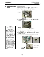
Page 20: ...he Locking Screw Setting the Black Mark Sensor position 1 Remove the Locking Screw that secures the Media Sensor 2 Pull about 500 mm of media out of the front of the printer turn the media back on itself and feed it under the Print Head past the sensor so that the black mark can be seen from above 3 Manually move the Media Sensor so that the Black Mark Sensor is in line with the center of the blac...

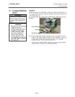
Page 21: ...i clockwise a few times to remove any slack in the backing paper 5 Set the Selection Switch mounted on the Rewinder Assembly to STANDARD PEEL OFF position Take up Clip Take up Spool Front Plate Black Screw Backing Paper NOTES 1 Be sure to set the Selection Switch to STANDARD PEEL OFF position 2 The backing paper is easier to feed back to the Take Up Spool if the Front Plate is removed 3 Fit the Ta...

Page 22: ...e Top Cover If the media is thermal transfer media it is also necessary to load a ribbon Refer to Section 2 8 Loading the Ribbon CAUTION 1 Be sure to cut the backing paper of the label Cutting labels will cause the glue to stick to the cutter which may affect the cutter quality and shorten the cutter life 2 Use of tag paper when the thickness exceeds the specified value may affect the cutter life ...

Page 23: ...his function please ask a TOSHIBA TEC authorised service representative CAUTION Be careful not touch the Print Head Element when raising the Print Head Block Failure to do this may cause missing dots by static electricity or other print quality problems 1 Do not touch any moving parts To reduce the risk of fingers jewellery clothing etc being drawn into the moving parts be sure to load the ribbon ...

Page 24: ...11119 03 Read Write INTEL IMC004FLSA Simple TECNOLOGY STI FL 4A Mitsubishi MF84M1 G7DAT01 PC Card KING MAX FJN 004M6C Centennial Technologies Inc FL04M 20 11138 67 PC Card FJP 004M6R Flash Memory Card 4 MB Mitsubishi MF84M1 GMCAV01 Maxell EF 1M TB Flash Memory Card 1 MB Mitsubishi MF81M1 GBDAT01 Read See NOTE CAUTION 1 To protect PC cards discharge static electricity from your body by touching the...

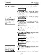
Page 25: ...ill appear 5 Press the PAUSE key and the issue count setting display will appear Set the issue count with the FEED or RESTART key 6 Press the PAUSE key and the print speed setting display will appear Set the print speed with the FEED or RESTART key 7 Press the PAUSE key and the sensor type setting display will appear Select the sensor type with the FEED or RESTART key 8 Press the PAUSE key and the...

Page 26: ...rint the specified issue counts of the slant lines 3 dots 15 Press the FEED key and PAUSE key and the printer will print the specified issue counts of the characters of various sizes 16 Press the FEED key and PAUSE key and the printer will print the specified issue counts of the bar codes 17 Press the FEED key and PAUSE key and the printer will print the specified issue counts of blank labels 18 P...

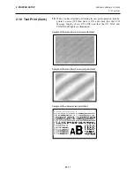
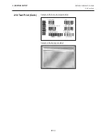
Page 27: ...ng the test print operation turn the printer s power OFF then back to ON and check that the LCD Message Display shows ON LINE and that the ON LINE and POWER LED lights are illuminated Sample of the slant line 1 dot test print label Sample of the slant line 3 dots test print label Sample of the character test print label ...

Page 28: ...2 PRINTER SETUP ENGLISH VERSION EO1 33034 2 10 Test Print E2 16 2 10 Test Print Cont Sample of the bar code test print label Sample of the factory test label ...

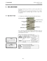
Page 29: ...32 characters can be displayed on two lines There are three LED lights on the operation panel LED Illuminates when Flashes when POWER The printer is turned on ON LINE The printer is ready to print The printer is communicating with your computer ERROR Any error occurs with the printer The ribbon is nearly over See NOTE There are three keys on the operation panel PAUSE Used to stop printing temporar...

Page 30: ...media to be printed 5 When the RESTART key is pressed the printer resumes printing A reset operation clears the print data sent from the computer to the printer and returns the printer to an idle condition 1 The printer is turned on standing by or printing 2 To stop printing or clear the data sent from the computer press the PAUSE key The printer stops printing 3 Press and hold the RESTART key for...

Page 31: ...n Dump mode any characters sent from the host computer will be printed Received characters are expressed in hexadecimal values This allows the user to verify programming commands and debug the program For details please refer to your nearest TOSHIBA TEC service representative ...

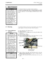
Page 32: ...ances from the internal part of the printer 8 Wipe the Feed Gap Sensor and Black Mark Sensor with a dry soft cloth WARNING 1 Be sure to disconnect the power cord before performing maintenance Failure to do this may cause an electric shock 2 To avoid injury be careful not to pinch your fingers while opening or closing the cover and print head block 3 The print head becomes hot immediately after pri...

Page 33: ...e the jammed paper 4 Clean the Cutter with a soft cloth slightly moistened with alcohol 5 Reassemble the Cutter Module in the reverse order of removal CAUTION 1 DO NOT POUR WATER directly onto the printer 2 DO NOT APPLY cleaner or detergent directly onto any cover or panel 3 NEVER USE THINNER OR OTHER VOLATILE SOLVENT on the plastic covers 4 DO NOT clean the panel covers or the supply window with ...

Page 34: ... humidity dust or gas The thermal paper used for direct thermal printing must not have specifications which exceed Na 800 ppm K 250 ppm and Cl 500 ppm Some ink used on pre printed media may contain ingredients which shorten the print head s product life Do not use labels pre printed with ink which contain hard substances such as carbonic calcium CaCO3 and kaolin Al2O3 2SiO2 2H2O For further inform...

Page 35: ...n the printer off and then on Then select the Media Sensor for the media being used Finally resend the print job 3 Adjust the sensor position Then press the RESTART key 4 Replace the loaded media with one that matches the programmed size then press the RESTART key or turn the printer off and then on select a programmed size that matches the loaded media Finally resend the print job 5 Refer to Sect...

Page 36: ...epresentative 5 2 Possible Problems This section describes problems that may occur when using the printer and their causes and solutions Possible Problems Causes Solutions The printer will not turn on 1 The Power Cord is disconnected 2 The AC outlet is not functioning correctly 3 The fuse has blown or the circuit breaker has tripped 1 Plug in the Power Cord 2 Test with a power cord from another el...

Page 37: ...and media 6 Remove the jammed media from the printer DO NOT USE any sharp implements or tools as these could damage the printer 7 Clean the Print Head and Platen then remove any further dust or foreign substances 8 Paper jams in the Cutter Unit can be caused by wear or residual glue from label stock on the cutter Do not use non specified media in the cutter CAUTION Do not use any tool that may dam...

Page 38: ... tags have been issued The media will continue to be fed until the PAUSE key is released Threshold setting for the selected sensor is completed by this operation 9 Press the RESTART key 10 The printer is in stand by 11 Send an issue command from the PC to the printer 21 1 6 7 9 3 86 6 7 9 75 160 66 9 6 7 9 5 7 9 6 7 9 75 160 66 9 6 7 9 3 86 6 7 9 21 1 6 7 9 21 1 6 7 9 NOTES 1 If the PAUSE key is r...

Page 39: ...0 mm 4 1 inches Batch Cut Cut mode is enabled only when the optional Cutter Module is installed Strip Strip mode is enabled only when the optional Strip Module is installed 16 characters 2 lines 291 mm 460 mm 308 mm 11 5 18 1 12 1 39 7 lb 18 kg Media and ribbon are not included JAN8 JAN13 EAN8 EAN8 2 digits EAN8 5 digits EAN13 EAN13 2 digits EAN13 5 digits UPC E UPC E 2 digits UPC E 5 digits UPC A...

Page 40: ...rd ATA standard Flash memory card 1MB and 4MB cards See Section 2 9 Built in LAN interface board B 9700 LAN QM This board enables the printer to be used in a LAN network USB interface board B 9700 USB QM Installing this board enables a connection to a PC which has a USB interface A1 3 Media Please make sure that the media being used is approved by TOSHIBA TEC The warranty does not apply when a pro...

Page 41: ...re diameter Ø76 2 0 3 A1 3 2 Detection Area of the Transmissive Sensor The Transmissive Sensor is movable from the centre to the left edge of media The Transmissive Sensor detects a gap between labels as illustrated below Label NOTES 1 To ensure print quality and print head life use only TOSHIBA TEC specified media 2 The media length specifications for use of the cutter are 1 When issuing a label ...

Page 42: ...ck Mark A1 3 4 Effective Print Area The figure below illustrates the relation between the head effective print width and media width Sensor should be positioned at the centre of the black mark Centre of media Min 12 mm Media feed direction Min 2 0 mm Sensor is movable within this range 4 mm 112 mm Max media width 104 mm 0 2 Head Effective Print Range Out of print range Out of print range 4 mm Dete...

Page 43: ...int on the 1 5 mm wide area from the media edges shaded area in the above figure Printing this area may cause ribbon wrinkles resulting in a poor print quality of the guaranteed print area 2 The centre of media is positioned at the centre of the Print Head 3 Print quality in the 3 mm area from the print head stop position including 1 mm non printable area for print speed slow down is not guarantee...

Page 44: ...es 6 CUTTER ERROR z A problem has occurred with the cutter module Yes Yes 7 NO PAPER z The media has run out or the media is not loaded properly Yes Yes 8 NO RIBBON z The ribbon has run out Yes Yes 9 HEAD OPEN z Feed or printing was attempted with the print head block open Yes Yes 10 HEAD ERROR z There is a problem with the print head Yes Yes 11 EXCESS HEAD TEMP z The print head is overheated No Y...

Page 45: ...layed However LF and NUL will not be displayed Example 1 ESC T20 G30 LF NUL Command error The following message appears Example 2 ESC XR 0200 0300 0450 1200 1 LF NUL Command error The following message appears Example 3 ESC PC001 0A00 0300 2 2 A 00 B LF NUL Command error The following message appears When the error command is shown 3FH appears for codes other than codes 20H to 7FH and A0H to DFH 7...

Page 46: ...ion The serial data cable used to connect the printer to the host compute should be one of the following two types NOTE Use an RS 232C cable with the connector including inch type securing screws for the QQ model or metric type securing screws for the QP model DB 9S Connector to PC Pin No Signal 1 N C 2 RXD 3 TXD 4 DTR 5 GND 6 DSR 7 RTS 8 CTS 9 N C Housing Shield DB 25P Connector to Printer Pin No...

Page 47: ...APPENDIX 4 PRINT SAMPLES ENGLISH VERSION EO1 33034 APPENDIX 4 PRINT SAMPLES EA4 1 APPENDIX 4 PRINT SAMPLES Font ...

Page 48: ...T SAMPLES EA4 2 APPENDIX 4 PRINT SAMPLES Cont Bar codes JAN8 EAN8 MSI Interleaved 2 of 5 CODE39 Standard NW7 JAN13 EAN13 UPC E EAN13 2 digits EAN13 5 digits CODE128 CODE39 Full ASCII CODE93 UPC E 2 digits UPC E 5 digits EAN8 2 digits EAN8 5 digits UPC A UPC A 2 digits ...

Page 49: ...PPENDIX 4 PRINT SAMPLES Cont UPC A 5 digits UCC EAN128 Industrial 2 of 5 POSTNET Customer bar code Customer bar code of high priority KIX Code RM4SCC RSS 14 RSS 14 Stacked RSS 14 Stacked Omnidirectional RSS Limited RSS Expanded Data Matrix PDF417 QR code Micro PDF417 MaxiCode CP Code ...

Page 50: ...t after a set number of media have been printed Cutter module A device used to cut the media DPI Dot Per Inch The unit used to express print density Expansion I O interface An optional interface circuit that may be installed into printer to allow the printer to be connected to an external device such as a wrapping machine and to receive feed print start and pause signals from the external device a...

Page 51: ...rinting it is heated by the thermal print head causing an image to be transferred onto the media Strip mode A device used to remove labels from the backing paper Supply Media and ribbon Tag A type of media with no adhesive Usually tags are made of cardboard or other durable material Thermal direct printing A printing method using no ribbon but thermal media which reacts to heat The thermal print h...

Page 52: ...print area A1 5 H Head lever 1 4 2 6 I Interface 2 3 A1 1 A3 1 Issue mode 2 9 A1 1 J Jammed media 5 3 L Label 2 6 A1 2 A1 3 LCD message display 1 3 1 4 3 1 M Media 2 6 4 3 A1 2 Media length A1 3 Media pitch A1 3 Media sensor 2 8 O ON LINE LED 1 4 3 1 Operation Panel 1 3 1 4 3 1 P Parallel interface 1 3 Parallel port 2 3 PAUSE key 1 4 3 1 PCMCIA card 2 12 PCMCIA interface board 2 12 A1 2 Platen 1 4...

Page 53: ... 3 Strip mode 2 9 Strip module 2 9 A1 2 Supply voltage A1 1 T Tag A1 2 Test print 2 13 Thermal direct 2 13 A1 1 Thermal transfer 2 13 A1 1 Threshold setting 5 4 Transmissive sensor 2 13 A1 3 Two dimensional code A1 1 U USB interface 1 3 2 3 A1 2 W Weight A1 1 ...

Page 54: ......

Page 55: ...the nearest TOSHIBA TEC service representative or sales agent Printer model and option Head lever position Parameter setting Ribbon saving function B SX5T TS12 QQ B SX5T TS12 QP B SX4T TS10 QQ B SX4T TS10 QP Position Label or Position Tag RBN SAVE OFF Default Disabled Position Label RBN SAVE ON Label Enabled for label B SX5T TS12 QQ B SX5T TS12 QP B SX4T TS10 QQ B 9904 R QM B SX4T TS10 QP B 9904 R...

Page 56: ......

Page 57: ......

Page 58: ...M EO1 33034 ...

Page 59: ...TEC Thermal Printer B SX5T QQ QP Owner s Manual ...

Page 60: ...ss proprietors can participate voluntarily The targeted products are office equipment such as computers monitors printers facsimiles copiers scanners and multifunction devices Their standards and logos are uniform among participating nations ENERGY STAR is a U S registered mark This equipment has been tested and found to comply with the limits for a Class A digital device pursuant to Part 15 of th...

Page 61: ...r cord plug with wet hands as this may cause electric shock If the machines share the same outlet with any other electrical appliances that consume large amounts of power the voltage will fluctuate widely each time these appliances operate Be sure to provide an exclusive outlet for the machine as this may cause fire or electric shock Do not place metal objects or water filled containers such as fl...

Page 62: ...ures high humidity dust or gas Ensure the printer is operated on a level surface Any data stored in the memory of the printer could be lost during a printer fault Try to avoid using this equipment on the same power supply as high voltage equipment or equipment likely to cause mains interference Unplug the machine whenever you are working inside it or cleaning it Keep your work environment static f...

Page 63: ...e Power Cord E2 4 2 6 Turning the Printer ON OFF E2 5 2 6 1 Turning ON the Printer E2 5 2 6 2 Turning OFF the Printer E2 5 2 7 Loading the Media E2 6 2 8 Loading the Ribbon E2 12 2 9 Inserting the Optional PCMCIA Cards E2 14 2 10 Test Print E2 15 3 ON LINE MODE E3 1 3 1 Operation Panel E3 1 3 2 Operation E3 2 3 3 Reset E3 2 3 4 Dump Mode E3 3 4 MAINTENANCE E4 1 4 1 Cleaning E4 1 4 1 1 Print Head P...

Page 64: ...APPENDIX 3 INTERFACE EA3 1 APPENDIX 4 PRINT SAMPLES EA4 1 GLOSSARIES INDEX CAUTION 1 This manual may not be copied in whole or in part without prior written permission of TOSHIBA TEC 2 The contents of this manual may be changed without notification 3 Please refer to your local Authorised Service representative with regard to any queries you may have in this manual This is a Class A product In a do...

Page 65: ...the left edge of the media The strip module ribbon saving module and expansion I O interface board are provided on this printer as standard When the optional interface board is installed Web functions such as remote maintenance and other advanced network features are available Superior hardware including the specially developed 12 dots mm 306 dots inch thermal print head which will allow very clea...

Page 66: ...ll the following accessories are supplied with the printer US Power Cord 1 pc P No FBCB0030203 QQ model only CD ROM 1 pc QQ P No 7FM00332000 QP P No 7FM00256000 Rewinder Guide Plate 1 pc P No FMBD0034501 EU Power Cord 1 pc P No EKA 0030001 QP model only Fan Filter 1 pc P No FMBB0036801 SMW 4x8 Sems Screws 2 pcs P No X0 00161000 ...

Page 67: ...lowing chapters Dimensions in mm inches LCD Message Display Operation Panel Power Switch OFF ON Media Outlet Top Cover Expansion I O Interface Connector Serial Interface Connector RS 232C Parallel Interface Connector Centronics Supply Window PCMCIA Card Slot Option USB Connector Option or LAN Connector Option AC Power Inlet 291 460 308 308 12 1 291 11 5 460 18 1 USB Connector Option or LAN Connect...

Page 68: ...r Please see Section 3 1 for further information about the Operation Panel LCD Message Display ON LINE LED Green ERROR LED Red PAUSE key POWER LED Green FEED key RESTART key Ribbon Stopper Print Head Block Head Lever Ribbon Shaft Supply Holder Locking Ring Supply Shaft Print Head Platen Take up Spool ...

Page 69: ...ver open Be careful not to allow fingers or articles of clothing to get caught into any of the moving parts of the printer especially the optional cutter mechanism Make sure to turn off the printer power and to remove the power cord from the printer whenever working on the inside of the printer such as changing the ribbon or loading the media or when cleaning the printer For best results and longe...

Page 70: ...ark Sensor depending on the media being used Refer to Section 2 7 8 Load the ribbon Refer to Section 2 8 9 Turn the power ON Refer to Section 2 6 10 Perform a test print Refer to Section 2 10 11 Install the Printer Drivers Refer to the Printer Driver Manual When installing the printer it is important to ensure that the Fan Filter is attached before using the printer The Fan Filter consists of 2 pa...

Page 71: ...s standard parallel connector and your host computer s parallel port LPT An Ethernet connection using the optional LAN board A USB cable connection between the printer s optional USB connector and your host computer s USB port Conforming to USB 1 1 The diagram below shows all the possible cable connections to the current version of the printer cParallel Interface Connector Centronics dSerial Inter...

Page 72: ...into a grounded outlet as shown in the figure below QQ Type QP Type CAUTION 1 Make sure that the printer Power Switch is turned to the OFF position before connecting the Power Cord to prevent possible electric shock or damage to the printer 2 Use only the Power Cord supplied with the printer Use of any other cord may cause electric shock or fire 3 Connect the Power Cord to a supply outlet with a p...

Page 73: ...er Power Switch verify that the ON LINE message appears in the LCD Message Display and that the ON LINE LED light is on and is not flashing 2 To turn OFF the printer power press the Power Switch as shown in the diagram below Note that is the power OFF side of the switch CAUTION Use the power switch to turn the printer On Off Plugging or unplugging the Power Cord to turn the printer On Off may caus...

Page 74: ...Allow it to cool before loading the media 3 To avoid injury be careful not to trap your fingers while opening or closing the cover WARNING NOTES 1 When the Head Lever is turned to Free position the Print Head is raised 2 To allow printing the Head Lever must be set to Lock position This ensures that the Print Head is closed There are two head pressure levels in the Lock position Set the Head Lever...

Page 75: ... Then turn the Locking Ring clockwise to secure the Supply Holder 8 Place the media between the Media Guides adjust the Media Guides to the media width and tighten the Locking Screw 9 Check that the media path through the printer is straight The media should be centred under the Print Head NOTE Do not over tighten the Locking Ring of the Supply Holder Supply Shaft Supply Holder Groove Damper Locki...

Page 76: ...he Locking Screw Setting the Black Mark Sensor position 1 Remove the Locking Screw that secures the Media Sensor 2 Pull about 500 mm of media out of the front of the printer turn the media back on itself and feed it under the Print Head past the sensor so that the black mark can be seen from above 3 Manually move the Media Sensor so that the Black Mark Sensor is in line with the centre of the blac...

Page 77: ... a few times to remove any slack in the backing paper 5 Set the Selection Switch mounted on the Rewinder Assembly to STANDARD PEEL OFF position Take up Clip Take up Spool Black Screw NOTES 1 Be sure to set the Selection Switch to STANDARD PEEL OFF position 2 The backing paper is easier to feed back to the Take Up Spool if the Front Plate is removed 3 Fit the Take Up Clip so that the longer side of...

Page 78: ...itch mounted on the Rewinder Assembly to REWINDER position NOTE Be sure to set the Selection Switch to REWINDER position ADJUSTMENT If the media skews when using the Built in Rewinder turn the Adjustment Knob of the Rewinder Guide Plate to correct the media feed Clockwise turn moves the Rewinder Guide Plate forward and counter clockwise moves it backward When the media skews to the right Loosen th...

Page 79: ...cedure is now completed Close the Ribbon Shaft Holder Plate and turn the Head Lever to Lock position to close Then close the Top Cover If the media is thermal transfer media it is also necessary to load a ribbon Refer to Section 2 8 Loading the Ribbon Media Outlet Media Cutter Module CAUTION 1 Be sure to cut the backing paper of the label Cutting labels will cause the glue to stick to the cutter w...

Page 80: ... from the front of the printer 6 Turn the Head Lever to Lock position to close the Print Head 7 Close the Top Cover CAUTION Be careful not touch the Print Head Element when raising the Print Head Block Failure to do this may cause missing dots by static electricity or other print quality problems 1 Do not touch any moving parts To reduce the risk of fingers jewellery clothing etc being drawn into ...

Page 81: ... reduce ribbon loss when a no print area extends more than 20 mm For further information on this function please ask a TOSHIBA TEC authorised service representative NOTE Ribbon loss per ribbon saving varies according to the relation between the outer roll diameter of the used ribbon and the print speed Print speed Ribbon loss Ribbon saving 3 sec Approx 5 mm 5 sec Approx 8 mm 8 sec Approx 17 mm ...

Page 82: ...11119 03 Read Write INTEL IMC004FLSA Simple TECNOLOGY STI FL 4A Mitsubishi MF84M1 G7DAT01 PC Card KING MAX FJN 004M6C Centennial Technologies Inc FL04M 20 11138 67 PC Card FJP 004M6R Flash Memory Card 4 MB Mitsubishi MF84M1 GMCAV01 Maxell EF 1M TB Flash Memory Card 1 MB Mitsubishi MF81M1 GBDAT01 Read See NOTE CAUTION 1 To protect PC cards discharge static electricity from your body by touching the...

Page 83: ...ill appear 5 Press the PAUSE key and the issue count setting display will appear Set the issue count with the FEED or RESTART key 6 Press the PAUSE key and the print speed setting display will appear Set the print speed with the FEED or RESTART key 7 Press the PAUSE key and the sensor type setting display will appear Select the sensor type with the FEED or RESTART key 8 Press the PAUSE key and the...

Page 84: ...rint the specified issue counts of the slant lines 3 dots 15 Press the FEED key and PAUSE key and the printer will print the specified issue counts of the characters of various sizes 16 Press the FEED key and PAUSE key and the printer will print the specified issue counts of the bar codes 17 Press the FEED key and PAUSE key and the printer will print the specified issue counts of blank labels 18 P...

Page 85: ...ng the test print operation turn the printer s power OFF then back to ON and check that the LCD Message Display shows ON LINE and that the ON LINE and POWER LED lights are illuminated Sample of the slant line 1 dot test print label Sample of the slant line 3 dots test print label Sample of the character test print label ...

Page 86: ...2 PRINTER SETUP ENGLISH VERSION EO1 33036 2 10 Test Print E2 18 2 10 Test Print Cont Sample of the bar code test print label Sample of the factory test label ...

Page 87: ...32 characters can be displayed on two lines There are three LED lights on the operation panel LED Illuminates when Flashes when POWER The printer is turned on ON LINE The printer is ready to print The printer is communicating with your computer ERROR Any error occurs with the printer The ribbon is nearly over See NOTE There are three keys on the operation panel PAUSE Used to stop printing temporar...

Page 88: ...media to be printed 5 When the RESTART key is pressed the printer resumes printing A reset operation clears the print data sent from the computer to the printer and returns the printer to an idle condition 1 The printer is turned on standing by or printing 2 To stop printing or clear the data sent from the computer press the PAUSE key The printer stops printing 3 Press and hold the RESTART key for...

Page 89: ...n Dump mode any characters sent from the host computer will be printed Received characters are expressed in hexadecimal values This allows the user to verify programming commands and debug the program For details please refer to your nearest TOSHIBA TEC service representative ...

Page 90: ...ances from the internal part of the printer 8 Wipe the Feed Gap Sensor and Black Mark Sensor with a dry soft cloth WARNING 1 Be sure to disconnect the power cord before performing maintenance Failure to do this may cause an electric shock 2 To avoid injury be careful not to pinch your fingers while opening or closing the cover and print head block 3 The print head becomes hot immediately after pri...

Page 91: ...e the jammed paper 4 Clean the Cutter with a soft cloth slightly moistened with alcohol 5 Reassemble the Cutter Module in the reverse order of removal CAUTION 1 DO NOT POUR WATER directly onto the printer 2 DO NOT APPLY cleaner or detergent directly onto any cover or panel 3 NEVER USE THINNER OR OTHER VOLATILE SOLVENT on the plastic covers 4 DO NOT clean the panel covers or the supply window with ...

Page 92: ... humidity dust or gas The thermal paper used for direct thermal printing must not have specifications which exceed Na 800 ppm K 250 ppm and Cl 500 ppm Some ink used on pre printed media may contain ingredients which shorten the print head s product life Do not use labels pre printed with ink which contain hard substances such as carbonic calcium CaCO3 and kaolin Al2O3 2SiO2 2H2O For further inform...

Page 93: ...n the printer off and then on Then select the Media Sensor for the media being used Finally resend the print job 3 Adjust the sensor position Then press the RESTART key 4 Replace the loaded media with one that matches the programmed size then press the RESTART key or turn the printer off and then on select a programmed size that matches the loaded media Finally resend the print job 5 Refer to Sect...

Page 94: ...epresentative 5 2 Possible Problems This section describes problems that may occur when using the printer and their causes and solutions Possible Problems Causes Solutions The printer will not turn on 1 The Power Cord is disconnected 2 The AC outlet is not functioning correctly 3 The fuse has blown or the circuit breaker has tripped 1 Plug in the Power Cord 2 Test with a power cord from another el...

Page 95: ...and media 6 Remove the jammed media from the printer DO NOT USE any sharp implements or tools as these could damage the printer 7 Clean the Print Head and Platen then remove any further dust or foreign substances 8 Paper jams in the Cutter Unit can be caused by wear or residual glue from label stock on the cutter Do not use non specified media in the cutter CAUTION Do not use any tool that may dam...

Page 96: ... tags have been issued The media will continue to be fed until the PAUSE key is released Threshold setting for the selected sensor is completed by this operation 9 Press the RESTART key 10 The printer is in stand by 11 Send an issue command from the PC to the printer 21 1 6 7 9 3 86 6 7 9 75 160 66 9 6 7 9 5 7 9 6 7 9 75 160 66 9 6 7 9 3 86 6 7 9 21 1 6 7 9 21 1 6 7 9 NOTES 1 If the PAUSE key is r...

Page 97: ...m to 140 0 mm 1 2 inches to 5 5 inches 128 0 mm 5 inches Batch Strip Cut Cut mode is enabled only when the optional Cutter Module is installed 16 characters 2 lines 291 mm 460 mm 308 mm 11 5 18 1 12 1 44 1 lb 20 kg Media and ribbon are not included JAN8 JAN13 EAN8 EAN8 2 digits EAN8 5 digits EAN13 EAN13 2 digits EAN13 5 digits UPC E UPC E 2 digits UPC E 5 digits UPC A UPC A 2 digits UPC A 5 digits...

Page 98: ...ch has a USB interface A1 3 Media Please make sure that the media being used is approved by TOSHIBA TEC The warranty does not apply when a problem is caused by using media that is not approved by TOSHIBA TEC For information regarding TOSHIBA TEC approved media please contact a TOSHIBA TEC authorised service representative A1 3 1 Media Type Two types of media can be loaded for this thermal transfer...

Page 99: ...um effective length for on the fly issue 749 0 Maximum outer roll diameter Ø200 Roll direction Inside Inner core diameter Ø76 2 0 3 A1 3 2 Detection Area of the Transmissive Sensor The Transmissive Sensor is movable from the centre to the left edge of media The Transmissive Sensor detects a gap between labels as illustrated below Label NOTES 1 To ensure print quality and print head life use only T...

Page 100: ...Mark A1 3 4 Effective Print Area The figure below illustrates the relation between the head effective print width and media width Sensor should be positioned at the centre of the black mark Centre of media Min 12 mm Media feed direction Min 2 0 mm Sensor is movable within this range 6 0 mm 140 mm Max media width 128 0 mm 0 2 Head Effective Print Range Out of print range Out of print range 6 0 mm D...

Page 101: ...int on the 1 5 mm wide area from the media edges shaded area in the above figure Printing this area may cause ribbon wrinkles resulting in a poor print quality of the guaranteed print area 2 The centre of media is positioned at the centre of the Print Head 3 Print quality in the 3 mm area from the print head stop position including 1 mm non printable area for print speed slow down is not guarantee...

Page 102: ...es 6 CUTTER ERROR z A problem has occurred with the cutter module Yes Yes 7 NO PAPER z The media has run out or the media is not loaded properly Yes Yes 8 NO RIBBON z The ribbon has run out Yes Yes 9 HEAD OPEN z Feed or printing was attempted with the print head block open Yes Yes 10 HEAD ERROR z There is a problem with the print head Yes Yes 11 EXCESS HEAD TEMP z The print head is overheated No Y...

Page 103: ...layed However LF and NUL will not be displayed Example 1 ESC T20 G30 LF NUL Command error The following message appears Example 2 ESC XR 0200 0300 0450 1200 1 LF NUL Command error The following message appears Example 3 ESC PC001 0A00 0300 2 2 A 00 B LF NUL Command error The following message appears When the error command is shown 3FH appears for codes other than codes 20H to 7FH and A0H to DFH 7...

Page 104: ...ion The serial data cable used to connect the printer to the host compute should be one of the following two types NOTE Use an RS 232C cable with the connector including inch type securing screws for the QQ model or metric type securing screws for the QP model DB 9S Connector to PC Pin No Signal 1 N C 2 RXD 3 TXD 4 DTR 5 GND 6 DSR 7 RTS 8 CTS 9 N C Housing Shield DB 25P Connector to Printer Pin No...

Page 105: ...APPENDIX 4 PRINT SAMPLES ENGLISH VERSION EO1 33036 APPENDIX 4 PRINT SAMPLES EA4 1 APPENDIX 4 PRINT SAMPLES n Font ...

Page 106: ... SAMPLES EA4 2 APPENDIX 4 PRINT SAMPLES Cont n Bar codes JAN8 EAN8 MSI Interleaved 2 of 5 CODE39 Standard NW7 JAN13 EAN13 UPC E EAN13 2 digits EAN13 5 digits CODE128 CODE39 Full ASCII CODE93 UPC E 2 digits UPC E 5 digits EAN8 2 digits EAN8 5 digits UPC A UPC A 2 digits ...

Page 107: ...PPENDIX 4 PRINT SAMPLES Cont UPC A 5 digits UCC EAN128 Industrial 2 of 5 POSTNET Customer bar code Customer bar code of high priority KIX Code RM4SCC RSS 14 RSS 14 Stacked RSS 14 Stacked Omnidirectional RSS Limited RSS Expanded Data Matrix PDF417 QR code Micro PDF417 MaxiCode CP Code ...

Page 108: ...t after a set number of media have been printed Cutter module A device used to cut the media DPI Dot Per Inch The unit used to express print density Expansion I O interface An interface circuit that may be installed into printer to allow the printer to be connected to an external device such as a wrapping machine and to receive feed print start and pause signals from the external device and to sen...

Page 109: ...rinting it is heated by the thermal print head causing an image to be transferred onto the media Strip mode A device used to remove labels from the backing paper Supply Media and ribbon Tag A type of media with no adhesive Usually tags are made of cardboard or other durable material Thermal direct printing A printing method using no ribbon but thermal media which reacts to heat The thermal print h...

Page 110: ...print area A1 5 H Head lever 1 4 2 6 I Interface 2 3 A1 1 A3 1 Issue mode 2 9 A1 1 J Jammed media 5 3 L Label 2 6 A1 2 A1 3 LCD message display 1 3 1 4 3 1 M Media 2 6 4 3 A1 2 Media length A1 3 Media pitch A1 3 Media sensor 2 8 O ON LINE LED 1 4 3 1 Operation Panel 1 3 1 4 3 1 P Parallel interface 1 3 Parallel port 2 3 PAUSE key 1 4 3 1 PCMCIA card 2 14 PCMCIA interface board 2 14 A1 2 Platen 1 4...

Page 111: ... 3 Strip mode 2 9 Strip module 2 9 A1 2 Supply voltage A1 1 T Tag A1 2 Test print 2 15 Thermal direct 2 15 A1 1 Thermal transfer 2 15 A1 1 Threshold setting 5 4 Transmissive sensor 2 15 A1 3 Two dimensional code A1 1 U USB interface 1 3 2 3 A1 2 W Weight A1 1 ...

Page 112: ......

Page 113: ...the nearest TOSHIBA TEC service representative or sales agent Printer model and option Head lever position Parameter setting Ribbon saving function B SX5T TS12 QQ B SX5T TS12 QP B SX4T TS10 QQ B SX4T TS10 QP Position Label or Position Tag RBN SAVE OFF Default Disabled Position Label RBN SAVE ON Label Enabled for label B SX5T TS12 QQ B SX5T TS12 QP B SX4T TS10 QQ B 9904 R QM B SX4T TS10 QP B 9904 R...

Page 114: ......

Page 115: ......

Page 116: ...M EO1 33036 ...

Page 117: ...TEC Thermal Printer B SX4T SX5T SERIES Document No EO10 33013A Original Jan 2003 Revised Feb 2003 Product Description PRINTED IN JAPAN ...

Page 118: ... INTERFACE BOARD B 9700 PCM QM 3 2 3 5 EXPANSION I O INTERFACE BOARD B 7704 IO QM option for the B SX4T 3 2 3 6 BUILT IN LAN INTERFACE BOARD B 9700 LAN QM 3 3 3 7 USB INTERFACE BOARD B 9700 USB QM 3 3 CAUTION 1 This manual may not be copied in whole or in part without prior written permission of TOSHIBA TEC 2 The contents of this manual may be changed without notification 3 Please refer to your lo...

Page 119: ... 104 0 mm wide by 1498 0 mm long and a max printing speed of 10 sec The B SX5T series accommodates a max format size of 128 0 mm wide by 1498 0 mm long and a max printing speed of 8 sec 6 High throughput can be obtained with on the fly formatting 7 Installation space is minimized because the media is loaded internally 8 The metal cover and damper provide a heavy duty enclosure 9 Various optional d...

Page 120: ...or occurs Used to set the threshold Refer to the Owner s Manual PAUSE key Pauses printing Message display shows PAUSE and a remaining count Used to set the threshold Refer to the Owner s Manual 1 3 3 Dimensions Approximate Standard 291 mm W x 460 mm D x 308 mm H With cutter module 291 mm W x 521 mm D x 308 mm H LCD Message Display Operation Panel Media Outlet Top Cover Supply Window Power Switch O...

Page 121: ...he entire label or tag paper 4 Format size W x L B SX4T Max 104 0 mm x 1498 0 mm B SX5T Max 128 0 mm x 1498 0 mm 5 Issue mode Batch Auto cut Auto cut mode is available only when the optional cutter is attached Strip In case of the B SX4T the strip mode is available only when the optional strip module is attached 6 Type of bar code two dimensional code 1 JAN8 EAN8 JAN13 EAN13 UPC A UPC E 13 PDF417 ...

Page 122: ...etica bold 18 21 point 13 OCR A B 12 point 6 Helvetica Italic 18 point 14 Outline font Helvetica bold Helvetica bold proportional 7 Presentation bold 27 point Price Font 1 2 3 Times roman proportional Pop 8 Letter Gothic medium 14 3 point Proportional Proportional 15 Writable characters 2 byte character is available B SX5T 1 Times Roman medium 8 10 point 9 Prestige Elite medium 7 point 2 Times Rom...

Page 123: ...t continuously without winding the label or tag paper 2 Strip mechanism B SX4T series Option When the strip module is attached labels are stripped from the backing paper by the strip shaft The next label will not be printed until the preceding label is taken away The backing paper is wound onto the take up spool By installing the rewinder guide plate the tag paper and label can be wound onto the t...

Page 124: ... 16A NOTE Be sure to provide an exclusive AC outlet for this machine 20 Rush current QQ model 11A QP model 14A 1 5 ELECTRONICS SPECIFICATIONS 1 CPU HD6417709SF100B 2 Memory 1 Program 4MB Flash ROM 2 Backup 512 Byte EE PROM 3 Image buffer Work B SX4T 8MB SD RAM B SX5T 16MB SD RAM 3 Interface 1 RS 232C interface c Communication mode Full duplex d Transmission speed 2400 4800 9600 19200 38400 115200 ...

Page 125: ...power on this printer becomes ready to receive data and converts the DTR signal to High level READY The printer converts the DTR signal to Low level BUSY when the free area in the receive buffer amount to 10K bytes or less The printer converts the DTR signal to High level READY when the free area in the receive buffer amount to 512KB or more When there is no free area in the receive buffer the pri...

Page 126: ...tection 2 RD Received Data Input Data line from which the printer receives data from the host receive data line Logic 1 is Low and 0 is High It is LOW MARK while no data is being sent 3 TD Transmit Data Output Data line from which the printer sends data to the host send data line Logic 1 is low and 0 is High It is LOW MARK while no data is being sent 4 CTS Clear to Send Input Input signal from the...

Page 127: ...E1284Active e Data input code ASCII JIS 8 bit code for European characters 8 bit code for graphic f Receiving buffer 1MB g Input Output circuit configuration and Input Output conditions Type Signal Name Configuration Input Output Data 1 8 Input nStrobe HostClk nInit nReverseRequest nAutoFd HostAck nSelectIn IEEE1284Active Output Busy PeriphAck nFault nPeriphRequest nAck PeriphClk Select XFlag PErr...

Page 128: ...c is 24 V max while the diode operating current is 16 mA Output circuit There are seven output circuits and each output is an open collector The voltage of Vcc is 24V max while the operating current is 150 mA For other details please refer to the Expansion I O specifications stored in the enclosed CD ROM or posted on the web site with the URL http barcode toshibatec co jp External controller etc V...

Page 129: ...turns the sensor on 2 Head block position switch Transmissive sensor This sensor located on the left side of the print head block detects whether the print head block is in position or not According to the position of the print head block the arm on it turns the sensor on off 3 Media sensor This sensor is comprised of the black mark sensor and feed gap sensor It is positioned 92 1 mm from the plat...

Page 130: ...nsor Reflective sensor When printing in thermal transfer mode using the ribbon this sensor detects the difference in potential between the ribbon and the ribbon end to indicate the ribbon end It is positioned at 48 28 mm from the platen Main Frame Black Mark Sensor Backing Paper Label Home Position Center of Label Feed Gap Sensor 8 mm Side Frame 22 5 mm 78 5 mm 8 mm 101 mm Main Frame Backing Paper...

Page 131: ...dent on the detected count The slit sensor is a photo coupler combining an LED and a transistor 6 Strip sensor Transmissive sensor This sensor detects whether or not the label has been taken away from the media outlet and controls the label feed It is positioned 17 8 mm from the platen Slit Slit Sensor Rewind Slit Slit Sensor Feed Rewind Slit Gear Feed Slit Gear Platen Strip Shaft Strip Sensor LED...

Page 132: ...he platen A rewinder full status is detected when the backing paper blocks the light from the LED 8 Cutter home position switch micro switch for Swing Cutter A cam positioned at the end of the cutter motor arm turns the micro switch on off in accordance with the cutter motion cycle one rotation The micro switch status indicates if the cutter is in the home position Rewind Full Sensor LED Platen Ba...

Page 133: ...ng paper See NOTE 5 30 0 112 0 50 0 112 0 30 0 112 0 Label width See NOTE 5 27 0 109 0 47 0 109 0 27 0 109 0 Gap length 2 0 20 0 6 0 20 0 Black mark length Tag paper 2 0 10 0 Effective print width 10 0 104 0 Label 6 0 1496 0 21 4 1496 0 3 sec 6 sec 30 0 1492 0 23 0 1492 0 Effective print length Tag 8 0 1498 0 3 sec 6 sec 28 0 1496 0 23 0 1496 0 Print speed up slow down area 1 0 Label 0 13 0 17 Thi...

Page 134: ... at least three times as long as the gap 9 When taking up the printed media onto the take up spool in batch mode the outer roll diameter must not exceed 180mm 10 When cutting the thermal label secure a gap of 6 mm or more and cut in the middle of the gap 11 For the backing paper Glassine paper 7K white or equivalent should be used Also the light transmission rate of the backing paper should be 22 ...

Page 135: ...width and paper B SX4T B SX5T NOTE The specifications differ depending on the issue mode For details refer to the media specification table on page 2 1 Head effective print width Outside the print range Outside the print range 4 0 mm 4 0 mm 104 0 mm 0 2 mm 112 0 mm Maximum paper width Head effective print width Outside the print range Outside the print range 6 0 mm 6 0 mm 128 0 mm 0 2 mm 140 0 mm ...

Page 136: ...wever too much difference in width between the two may cause wrinkles 3 When using a 112 mm wide media be sure to use a 108 mm wide ribbon Use of other ribbons may cause ribbon wrinkles 4 When using a 134 mm wide media be sure to use a 130 mm wide ribbon Use of other ribbons may cause ribbon wrinkles B SX4T Ribbon width 41 mm 50 mm 68 mm 84 mm 112 mm NOTE 3 Proper media width 30 to 36 mm 36 to 45 ...

Page 137: ...d areas where they would be exposed to direct sunlight high temperature high humidity dust or gas For further information please contact your local distributor or your media and ribbon manufacturer CAUTION Be sure to read carefully and understand the Supply Manual Use only media and ribbon which meet specified requirements Use of non specified media and ribbon may shorten the head life and result ...

Page 138: ...04 IO QM Installing this board allows connection to external devices Built in LAN interface board B 9700 LAN QM This board enables the printer to be used in a LAN network USB interface board B 9700 USB QM Installing this board enables a connection with a PC which has a USB interface NOTE To purchase the optional kits please contact the TOSHIBA TEC Head Quarters 3 1 CUTTER MODULE B 4205 QM Swing Cu...

Page 139: ...ry card when connected to the CPU PC board Number of slots Type II slot 2 slots Type Maker Description Remarks ATA Card San Disk Hitachi A card conforming to the PC card ATA standard LAN Card 3 COM 3CCE589ET Series Install into the slot 2 only This card installed into the slot 1 will not work Maxell EF 4M TB Maxell EF 4M TB Centennial Technologies INC FL04M 15 11119 03 Read Write INTEL IMC004FLSA ...

Page 140: ...l 32 bit wide data pass for the packet buffer memory Conforming to IEEE 802 3 802 3u 100 Base Tx 10Base T physical layer Auto negotiation 10 100M bps Full Half Duplex 3 7 USB INTERFACE BOARD B 9700 USB QM Installing this board enables a connection to a PC which has a USB interface Conforming to USB 1 1 Supporting Full speed 12M bps transmission Supporting the two types of data transmission types C...

Page 141: ......

Page 142: ...PRINTED IN JAPAN EO10 33013A ...

Page 143: ...PRINTED IN JAPAN TEC Thermal Printer B SX4T SX5T SERIES Document No EO18 33012A Original Jan 2003 Revised Feb 2003 Maintenance Manual ...

Page 144: ...es and to insure proper performance and operation 2 Failure to follow manual instructions or any unauthorized modification substitution or change to this product will void the limited product warranty WARNING Follow all manual instructions Failure to do so could create safety hazards such as fire or electrocution ...

Page 145: ... B 9700 USB QM 4 23 4 7 LAN INTERFACE BOARD B 9700 LAN QM 4 27 4 8 EXPANSION I O INTERFACE BOARD B 7704 IO QM 4 31 5 SYSTEM MODE 5 1 5 1 OPERATION PANEL 5 1 5 2 OVERVIEW 5 2 5 3 SELF DIAGNOSTIC TEST 5 3 5 3 1 Printing Mode Selection 5 4 5 3 2 Dispensing Mode Selection 5 4 5 3 3 Maintenance Counter Parameter Settings Printing Out 5 5 5 3 4 Self Diagnostic Test and Result Print Out 5 10 5 3 5 Print ...

Page 146: ...5 34 5 5 2 Cut Strip Position Fine Adjustment 5 35 5 5 3 Back Feed Length Fine Adjustment 5 37 5 5 4 X Axis Fine Adjustment 5 38 5 5 5 Print Tone Fine Adjustment Thermal Transfer Thermal Direct Print 5 39 5 5 6 Ribbon Motor Voltage Fine Adjustment Feed Take up Motor 5 40 5 5 7 Threshold Manual Fine Adjustment Black Mark Feed Gap Sensor 5 41 5 6 TEST PRINT 5 42 5 6 1 Specifying the Print Condition ...

Page 147: ...NTENANCE PROCEDURE 8 1 9 TROUBLESHOOTING 9 1 10 MAJOR UNIT REPLACEMENT 10 1 10 1 POWER SUPPLY UNIT 10 1 10 2 MAIN PC BOARD 10 3 10 3 PANEL PC BOARD AND LCD UNIT 10 5 10 3 1 LCD 10 5 10 3 2 Panel PC Board 10 6 10 4 STEPPING MOTOR 10 7 10 5 RIBBON MOTORS TAKE UP FEED 10 9 10 5 1 Ribbon Motor Take up 10 9 10 5 2 Ribbon Motor Feed 10 11 10 6 RIBBON MOTOR SENSORS TAKE UP FEED 10 13 10 6 1 Ribbon Motor ...

Page 148: ...sion of TOSHIBA TEC 2 The contents of this manual may be changed without notification 3 Please refer to your local Authorised Service representative with regard to any queries you may have in this manual Copyright 2003 by TOSHIBA TEC CORPORATION All Rights Reserved 570 Ohito Ohito cho Tagata gun Shizuoka ken JAPAN This manual is intended for both B SX4T series and B SX5T series Please note that th...

Page 149: ... carton 2 Unpack the accessories and the front pad from the carton 3 Unpack the pads and the printer from the carton 4 Remove the four pieces of tape and the rear pad from the printer Carton Accessories Front Pad Printer Bottom Pad Right Side Pad Left Side Pad Tape Rear Pad Tape ...

Page 150: ...er 6 In case of the B SX5T series take out the rewinder guide plate and two SMW 3x8 screws from the printer inside Also remove the tape from the rewinder unit in the printer NOTE For the installation procedure of the rewinder guide plate refer to Section 4 3 Ribbon Shaft Holder Plate Ribbon Shaft Pad Top Cover Tape Tape Tape Tape OPEN Rewinder Guide Plate SMW 4x8 Screw Rewinder Tape ...

Page 151: ...nd pads for later transport 2 PRINTER INSTALLATION 1 Place the printer on the level surface 2 Keep the slit free or the printer will be overheated Also keep enough space for replacing and maintenance works while the top cover is opened Left Side Cover Top Cover Slit QC Card QQ model only Warranty Registration QQ model only Fan Filter Power Cord CD ROM Ferrite Core B SX5T series only Cable Band B S...

Page 152: ...er printing Doing so may cause you to be injured by the print head and the inner parts of the printer being hot 3 When cleaning the cutter be careful not to be injured by the cutter blade B 8204 QM B 4205 QM 4 Be careful not to pinch your fingers or hands with the covers CAUTION 1 Fix the harnesses and the cord bushes with the cable clamp Failure to do this may cause the covers to catch them Cutte...

Page 153: ... not remove the screws below Doing so will require the printer block position adjustment with the jig 3 Be careful not to damage the sensor window If so the sensor cannot detect the feed gap or the black mark correctly causing improper printing 4 Be careful not to damage the print head element Doing so will cause improper printing Printer Block Screw Sensor Window Print Head ...

Page 154: ...VING THE SIDE PANEL L 1 Remove the four B 4x5 screws from the side panel L 2 Open the top cover and remove the three SMW 4x8 screws that secure the side panel L 3 Close the top cover 4 Lift the side panel L and put it aside 5 Release the fan motor harness from the cable clamp disconnect it from CN19 on the Main PC board and then separate the side panel L Open Position Close Position B 4x5 Screw B ...

Page 155: ...urn the head lever counterclockwise to Free position 3 Open the ribbon shaft holder plate 4 Raise the print head block until it stops NOTE DO NOT excessively push down the print head block to close it Dosing so may cause a failure of the print head block or damage to the print head Ribbon Shaft Holder Plate Head Lever Free position Lock position Label Lock position Tag Print Head Block Stopper ...

Page 156: ...ion 3 1 2 Remove the side panel L from the printer Refer to section 3 2 3 Remove the SMW 4x8 screw that secures the operation panel ass y 4 Half open the top cover otherwise the operation panel ass y cannot be removed from the printer 5 Lift the operation panel ass y to release the hook and then remove the operation panel ass y by moving it forward SMW 4x8 Screw Top Cover Operation Panel Ass y ...

Page 157: ...ON PANEL 3 6 6 Disconnect the operation panel harness from the operation panel ass y 7 Reassemble in the reverse order of removal Lead the operation panel harness through the bush so that the side panel L does not catch it Operation Panel Ass y Operation Panel Harness Hook Bottom Plate Bush Operation Panel Harness ...

Page 158: ...ther 2 The B 9700 LAN QM and the B 9700 USB QM cannot be used together 3 When using the B 9700 PCM QM together with the B 9700 LAN QM or the B 9700 USB QM attach the B 9700 PCM QM onto the Main PC board 4 The strip module ribbon saving module and expansion I O interface board are standard on the B SX5T series 5 When installing the B 4205 QM swing cutter module or B 8204 QM rotary cutter module on ...

Page 159: ... harness from the cable clamp and disconnect it from the shorter harness of the strip sensor harness TR 8 Remove the expansion I O board from the printer temporarily using the following procedure 1 Disconnect the expansion I O cable from CN1 on the Expansion I O board 2 Remove the two B 3x6 screws to detach the expansion I O board from the printer SMW 4x8 Screw SMW 4x8 Screw Strip Sensor LED Cable...

Page 160: ...nd full sensor TR and rewinder harness from CN4 and CN15 on the Main PC board respectively NOTE Secure the rewinder harness and the longer harness of the rewind full sensor TR to the space under the Main PC board with the cable clamp so that they are not pinched by the covers or printer s internal components 11 Reassemble the operation panel ass y and the expansion I O board in the reverse order o...

Page 161: ... together with either B 8204 QM or B 9904 H QM All the following parts are supplied with the kit Make sure you have all items shown below Cutter Unit 1 pc Cutter Cover 1 pc Cutter Harness 1 pc Print Head Cleaner 1 pc P No FMQB0051601 Cutter Attachment Screw 2 pcs Bush 1 pc Installation manual 1 copy FL 4x6 Screw 1 pc 1 Remove the two black screws to detach the front plate NOTE Retain the two black...

Page 162: ...ront of the printer with the cutter attachment screws and the FL 4x6 screw 6 Connect the cutter harness to CN1 on the cutter I F PC board 7 Fit the bush to the cutter harness in the orientation shown below 8 Insert the cutter harness into the gap between the cutter unit and the printer and then into the hole in the main frame Fit the bush into the hole Cutter Attachment Screw FL 4x6 Screw Cutter U...

Page 163: ...ge to the print head 10 Connect the cutter harness to CN15 on the Main PC Board 11 Fit the cutter cover on the cutter attachment screws and fix it to the cutter unit with the two cutter screws NOTE Be careful not to pinch the cutter harness by the cutter cover 12 Reassemble the side panel L and close the top cover Finally check the cutter operation NOTE For cleaning the cutter refer to section 8 C...

Page 164: ...is optional device is used for cut print which cannot be used together with either B 4205 QM or B 4905 H QM All the following parts are supplied with the kit Make sure you have all items shown below Cutter Unit 1 pc Cutter Cover 1 pc Cutter Drive Unit 1 pc Harness Ass y 2 pin 9 pin 1 pc Cord Bush 1 pc Print Head Cleaner 1 pc P No FMQB0051601 Installation Manual 1 copy SM 4x8 Screw 6 pcs Cutter Bla...

Page 165: ... the side panel L from the printer Refer to section 3 2 4 Fix the cutter drive unit to the printer with the three SM 4x8 screws 5 Connect the 9 pin connector of the harness ass y to CN7 and 2 pin connector to CN9 on the cutter driver unit respectively 6 Fit the bush to the harness ass y in the orientation as shown below SM 4x8 Screw Cutter Drive Unit SM 4x8 Screw CN7 9 pins CN9 2 pins Harness Ass ...

Page 166: ...in connector of the harness ass y to CN15 and 2 pin connector to CN18 on the Main PC board respectively 9 Open the printer block Refer to section 3 3 10 Connect the four harnesses of the cutter unit to CN8 CN10 CN11 and CN12 on the cutter drive unit Main PC Board CN18 2 pins CN15 9 pins Harness Ass y Hole Main Frame Harness Ass y Cutter Unit Cutter Drive Unit Print Head Block CN8 CN12 CN10 CN11 ...

Page 167: ...t to pinch the cutter harness by the cutter cover 2 Make sure that the anti static brush is protruding from the media outlet 13 Close the print head block and ribbon shaft holder plate NOTE DO NOT excessively push down the print head block to close it Doing so may cause a failure of the print head block or damage to the print head 14 Reassemble the side panel L and close the top cover Finally chec...

Page 168: ...her with either B 4205 QM or B 8204 H QM NOTE The strip module is standard on the B SX5T series All the following parts are supplied with the kit Make sure you have all items shown below Rewinder Ass y 1 pc Rewinder Guide Plate 1 pc Bush 1 pc Strip Sensor TR 1 pc Strip Sensor LED 1 pc Rewind Paper Guide 1 pc Installation Manual 1 copy SM 4x8B Screw 10 pcs SM 3x6B Screw 1 pc SM 4x8C Screw 1 pc ...

Page 169: ... printer Refer to section 3 2 4 Remove the operation panel ass y from the printer Refer to section 3 4 5 Attach the rewind paper guide to the base with the two M 4x8 screws 6 Align the notch of the take up holder with the screw hole of the rewinder ass y and attach them to the printer with the four SM 4x8B screws and the SM 4x8C screw 7 Attach the rewind full sensor LED to the base with the SM 3x6...

Page 170: ...he orientation shown below 9 Insert the longer harness of the rewind full sensor Tr into the hole in the printer frame Fit the bush into the hole SM 4x8B Screw SM 4x8C Screw SM 4x8B Screw Take up Holder Notch Rewind Full Sensor LED SM 3x6B Screw Rewinder Ass y Base Bush Longer Harness of the Rewind Full Sensor Tr Longer Harness of the Rewind Full Sensor Tr Bush Hole Frame Rewinder Harness ...

Page 171: ...p Spool detach the Holder Stopper by removing the B 3x4 screw Otherwise it may be difficult to pull out the wound backing paper roll When using a paper core put the core on the Take up Spool with the Holder Stopper on it and Attach the top edge of the backing paper to the core with adhesive tape The Take up Clip is not necessary This winding method is applicable to the Built in Rewinder mode 11 Op...

Page 172: ...clamp While passing the other strip sensor harness through the cut and the bush reassemble the operation panel ass y to the printer Then pass the strip sensor harness over the tab on the back of the operation panel ass y NOTE Be careful not to pinch the strip sensor harnesses by the operation panel SM 4x8B Screw Strip Sensor Tr Strip Sensor Harness for LED Shorter Harness of the Strip Sensor Harne...

Page 173: ... down the print head block to close it Doing so may cause a failure of the print head block or damage to the print head 19 When using the printer in batch mode or strip mode attach the front plate removed in step 1 20 When using the printer in built in rewinder mode attach the rewinder guide plate to the front of the printer with the two SMW 4x8 screws 21 Make a test print to check for proper stri...

Page 174: ...allation Manual 1 copy SM 4x8 Screw 2 pcs 1 Remove the side panel L from the printer Refer to section 3 2 2 Remove the operation panel ass y from the printer Refer to section 3 4 3 Fit the three locking supports into the RSV PC board 4 Secure the RSV PC board to the printer with the locking support NOTE Do not push the center of the RSV PC board when attaching it to the printer Doing so may break ...

Page 175: ...nger of the solenoid While holding down the head up arm slightly lift the solenoid Secure the solenoid to the frame with the two SM 4x8 screws keeping the solenoid in contact with the spacer 6 Attach the cable clamp to the frame of the printer Fix the solenoid cable with this cable clamp NOTE Be careful not to snag the solenoid harness when running it Frame SM 4x8 Screw Head Up Arm Plunger Solenoi...

Page 176: ...board Pass the solenoid harness through the cut 8 Connect the solenoid cable to CN2 on the RSV PC board 9 After attaching the solenoid reassemble the operation panel ass y and the side panel L in the reverse order of removal NOTE Perform 9 FOR FACTORY of system mode to make sure the solenoid performs properly CN2 CN1 Solenoid Cable CN11 Main PC Board Solenoid Harness RSV PC Board Cut ...

Page 177: ... interface board or USB interface board together install the PCMCIA interface board first NOTE When both B 9700 PCM QM and B 9700 LAN QM are installed inserting a LAN PC card into the slot of the B 9700 PCM QM disables the B 9700 LAN QM All the following parts are supplied with the kit Make sure you have all items shown below PCMCIA Interface Board 1 pc 1 Remove the side panel L from the printer R...

Page 178: ... the following procedure 1 Disconnect the Expansion I O cable from CN1 on the Expansion I O board 2 Remove the two B 3x6 screws to detach the Expansion I O board from the printer 4 Firmly connect CN101 on the PCMCIA interface board directly to CN7 on the Main PC board 5 Secure the PCMCIA interface board to the rear plate with the two SM 3x6 screws PCMCIA Interface Board Main PC Board CN101 CN7 SM ...

Page 179: ...rews that were removed in step 6 If the LAN interface board or USB interface board is also installed go to the next step NOTE Keep the two SM 3x6 screws and blind plate A safe when the LAN interface board or USB interface board is installed 8 Reassemble the side panel L in the reverse order of removal If the Expansion I O board was removed at the beginning reassemble it NOTE For inserting removing...

Page 180: ...nstall the PCMCIA PC board and then USB interface board All the following parts are supplied with the kit Make sure you have all items shown below USB Interface Board 1pc PCB Attachment Plate 1 pc NOTE When using the PCMCIA interface board B 9700 PCM QM together the PCB attachment plate will be used 1 Turn the power off and disconnect the power cord 2 Loosen the two M 3x5 screws of the USB interfa...

Page 181: ...CIA interface board is secured with the SM 3x6 screw If not go to the next step 6 Firmly connect CN50 connector on the USB interface board directly to CN7 on the Main PC board or CN1 on the PCMCIA interface board When connecting to the Main PC Board When connecting the PCMCIA Interface Board PCMCIA Interface Board PCB Attachment Plate SM 3x6 Screw USB Interface Board Main PC Board CN50 CN7 USB Int...

Page 182: ...he USB interface board to the PCB support plate when connecting to the Main PC board or PCB attachment plate when connecting to the PCMCIA interface board with the SM 3x6 screw When connecting to the Main PC Board When connecting to the PCMCIA Interface Board SM 3x6 Screw USB Interface Board SM 3x6 Screw USB Interface Board When connecting to the Main PC Board M 3x5 Screw SM 3x6 Screw PCB Support ...

Page 183: ...ch the blind plate A to the rear plate If the PCMCIA interface board has been installed go to the next step NOTE In case that the PCMCIA interface board has been installed retain the blind plate A 11 Reassemble the side panel L to the printer in the reverse order of removal Blind Plate A SM 3x6 Screw Rear Plate ...

Page 184: ...d B 9700 PCM QM are installed inserting a LAN PC card into the slot of the B 9700 PCM QM disables the B 9700 LAN QM All the following parts are supplied with the kit Make sure you have all items shown below LAN Interface Board 1pc PCB Attachment Plate NOTE When using the PCMCIA interface board B 9700 PCM QM together the PCB attachment plate will be used M 3x5 Screw License Agreement Please be sure...

Page 185: ...move the two SM 3x6 screws to remove the blind plate A from the back NOTE Keep the blind plate A safe as this will be necessary when the machine is modified to the standard type 4 If the PCMCIA interface board is also installed attach the PCB attachment plate to the plate to which the PCMCIA interface board is secured with the SM 3x6 screw If not go to the next step Blind Plate A SM 3x6 Screw PCB ...

Page 186: ... 6 Secure the LAN interface board to the rear plate with the two SM 3x6 screws When connecting to the Main PC Board When connecting to the PCMCIA Interface Board LAN Interface Board MAIN PC Board CN50 CN7 LAN Interface Board PCMCIA Interface Board CN50 CN1 When connecting to the Main PC Board When connecting to the PCMCIA Interface Board SM 3x6 Screw SM 3x6 Screw Rear Plate Rear Plate LAN Interfac...

Page 187: ...CIA interface board with the SM 3x6 screw 9 Reassemble the side panel L in the reverse order of removal NOTE Precaution for the LAN cable connection When connecting a LAN cable with the hooded connectors to the LAN interface board it may not be connected depending on the shape of the hood In this case move aside the hood connect the cable and return the hood to the former position When connecting ...

Page 188: ...ing parts are supplied with the kit Make sure you have all items shown below Expansion I O Board 1 pc Expansion I O Cable 1 pc Installation Manual 1 copy Locking Support WLS 16 0 1 pc NOTE The locking support is not used on this printer 1 Turn the power off and disconnect the power cord 2 Remove the side panel L from the printer Refer to section 3 2 3 Remove the two M 3x6 screws and detach the bli...

Page 189: ...on I O board to the rear plate with the two B 3x6 screws removed in Step 4 7 Connect the expansion I O cable to CN1 on the expansion I O board 8 Reassemble the side panel L in the reverse order of removal 9 Perform a loop back check to confirm that the expansion I O board functions properly Expansion I O Cable CN3 Main PC Board CN1 Expansion I O Board Expansion I O Cable B 3x6 Screw Rear Plate ...

Page 190: ...n Panel and key functions The LCD Message Display shows messages in alphanumeric characters and symbols to indicate the printer s status Up to 16 characters in 2 lines can be displayed There are three LEDs on the Operation Panel LED Illuminates when POWER The printer is turned on ON LINE The printer is ready to print ERROR Any error occurs with the printer In System Mode the FEED RESTART and PAUSE...

Page 191: ...de menu Flowcharts of each menu s sub menus are provided on the following pages 3 x x of DIAG Vx x indicates firmware version and revision This is the start of the Self Diagnostic Test menu This is the start of the Parameter Setting menu This is the start of the Printer Parameter Fine Adjustment menu This is the start of the Test Print menu This is the start of the Sensor Adjustment menu This is t...

Page 192: ... sub menus NOTE Use the FEED or RESTART key to select a desired option While pressing the FEED and PAUSE keys at the same time turn on the printer Hold both keys until the 1 DIAG Vx x message appears in the display PAUSE PAUSE FEED FEED RESTART RESTART FEED Selection of the printing mode Prints out the Maintenance Counter Parameter Settings Performs a Self Diagnostic Test and prints out the result...

Page 193: ...l Direct 5 3 2 Dispensing Mode Selection When TYPE S NO CUT is displayed press the PAUSE key The type of dispensing mode can be selected S NO CUT Batch printing C WITH CUT Cut printing or H PEEL OFF Strip printing After selecting the dispensing mode to be used press the PAUSE key NOTE When using the cutter module be sure to select C WITH CUT When using neither cutter module nor strip module be sur...

Page 194: ...OID 0h 232C ERR 255 SYSTEM ERR 0 POWER FAIL 0 PC KEY FEED 2 0mm FEED 0 0mm CUT 0 0mm CUT 1 0mm BACK 0 0mm BACK 0 0mm TONE T 0 step TONE T 0 step TONE D 0 step TONE D 0 step RBN FW 10 RBN FW 8 RBN BK 0 RBN BK 0 X ADJ 0 0mm THRESHOLD R 1 0V THRESHOLD T 1 4V FONT PC 850 0 SPEED 9600 DATA LENG 8 STOP BIT 1 PARITY EVEN CONTROL XON READY AUTO MESSAGE ENGLISH FORWARD WAIT ON 0 0mm HU CUT RWD OFF RIBBON S...

Page 195: ... driving time is not counted during ribbon saving operation but is during back feed See NOTE 4 0 to 2000 hours 7 Solenoid driving time Counted during ribbon saving operation See NOTE 4 0 to 1000 hours 8 RS 232C hardware error count Counted when a parity overrun or framing error occurs See NOTE 5 0 to 255 times 9 System error count Counted when any error occurs 0 to 15 times 10 Momentary power fail...

Page 196: ...fine adjustment Thermal transfer PC KEY 10 step to 10 step 15 Print tone fine adjustment Thermal direct PC KEY 10 step to 10 step 16 Ribbon take up motor driving voltage fine adjustment PC KEY 15 step to 0 step 17 Ribbon feed motor driving voltage fine adjustment PC KEY 15 step to 0 step 18 X axis fine adjustment 99 5 mm to 99 5 mm 19 Threshold manual fine adjustment for the black mark sensor 0 0V...

Page 197: ... 33 Feed key function FEED Feeds one label PRINT Prints image buffer on one label 34 Kanji code type Not supported QQ QP models TYPE 1 Windows code TYPE 2 Original code 35 Euro font code 20H to FFH 36 Auto print head broken element check ON Available OFF Unavailable 37 Centronics interface ACK BUSY timing setting TYPE1 The timing of ACK signal going up matches with that of the release of BUSY stat...

Page 198: ... Available OFF Unavailable 57 DHCP function setting ON Available OFF Unavailable 58 DHCP ID setting Max 16 characters 59 ESS ID ESS ID for wireless LAN Max 32 characters 60 CONNECTION Wireless LAN connecting method INFRASTRUCTURE Infrastructure mode ADHOC Adhoc mode 61 CHANNEL Channel No setting to connect wireless LAN Channel No 00 to 14 62 AUTH Wireless LAN authorization method OPEN SYSTEM Open ...

Page 199: ... Vx x The printer does not restart printing automatically Print Sample NOTES 1 Print conditions Preset count 1 Print speed 6 sec B SX4T or 5 sec B SX5T Sensor No sensor Printing method Thermal transfer Supply length 87 mm Issue mode Batch printing 2 Software version No Part No of ROM and checksum vary according to the software version of PROGRAM ROM 3 The last two digits of the checksum are usuall...

Page 200: ... area cannot be properly read written EEPROM Backup Memory Capacity of DRAM B SX4T 8MB B SX5T 16MB System Painting memory Checksum Part No of ROM or software Revision No Space or A to Z Program area Model name B SX4T B SX4T GS10 QQ QP B SX5T B SX5T TS12 QQ QP Software version No Checksum of Font area Font area Checksum Kanji area Checksum NONE Kanji ROM is not installed GOTHIC Gothic bit map Kanji...

Page 201: ... ATA card Flash memory card or no card is inserted Slot PCMCIA Card Printer block open sensor status 1 Print head close Cutter home position sensor status 0 Home position 1 Other position Rewinder overflow sensor status 0 Normal 1 Overflow Ribbon take up motor sensor status 0 The detecting point is positioned outside the slit 1 The detecting point is positioned inside the slit Fixed to 0 Ribbon fe...

Page 202: ...r outlet in strip printing mode When the label is not detected the printer feeds the label at the print start position 8 Sensor 2 Check The status of the Print Head Thermistor Environmental Temperature Thermistor Heat Sink Thermistor Black Mark Sensor Feed Gap Sensor and Ribbon End Sensor are printed SENSOR2 H 20 C A 22 C S 25 C R 4 2V T 2 5V E 2 7V RANK 7 Ribbon end sensor status 0 0 5 0V Heat si...

Page 203: ...the jig like below to the serial interface connector and perform a loop back check Loopback test OK The circuit has no problem NG The circuit has a problem or loopback jig is not attached Expansion I O PC board OK The circuit has no problem NG The circuit has a problem or loopback jig is not attached Internal Serial Interface R R R R R R R Vcc LED R 300 ohms Connector FCN 781P024 G P GND 12 11 10 ...

Page 204: ...print head If there is no problem with the print head the print head check is complete Press the PAUSE key to return to 1 DIAG Vx x If there is a problem with the print head the following message is displayed Press the PAUSE key to return to 1 DIAG Vx x NOTES 1 Make sure that the Top Cover is closed before starting the print head check 2 If HEAD ERROR appears the print head element may be damaged ...

Page 205: ... 3 5 0 7 5 6 7 8 87 5 2 3 5 0 7 5 6 7 5 21 6 9 21 3 5 0 7 5 6 7 2 6 18 3 5 0 7 5 6 7 3 2 676 2 3 5 0 7 5 6 7 3 5 0 7 5 6 7 1 2 7 3 3 5 0 7 5 6 7 852 2 3 5 0 7 5 6 7 872 2 3 5 0 7 5 6 7 86 7 3 3 5 0 7 5 6 7 35 17 5 2 3 5 0 7 5 6 7 1387 35 0 21 3 5 0 7 5 6 7 5 1 1 5 1 P 3 5 0 7 5 6 7 2 7 3 3 5 0 7 5 6 7 1752 02 633 3 5 0 7 5 6 7 3 8 3 2 3 5 0 7 5 6 7 1 7 3 3 5 0 7 5 6 7 35 3 2 2 3 5 0 7 5 6 7 63 67 ...

Page 206: ... select a character font code When 2 PARAMETER SET appears press the PAUSE key Press the PAUSE key to start Use the FEED or RESTART key to select a desired option After selecting the character code press the PAUSE key NOTES 1 When pressing the FEED and RESTART keys at the same time in the parameter setting the message returns to 2 PARAMETER SET 2 If holding the FEED or RESTART key for 0 5 seconds ...

Page 207: ...TTING 5 18 Example Character code table Printable characters depend on the fonts The fonts of the following characters are Times New Roman Helvetica Letter Gothic Prestige Elite Courier and Gothic 725 Black PC 850 PC 8 PC 852 PC 857 B 851 B 855 ...

Page 208: ...5 SYSTEM MODE EO18 33012A 5 4 PARAMETER SETTING 5 19 PC 1250 PC 1251 PC 1252 PC 1253 PC 1254 PC 1257 ...

Page 209: ...2 PARAMETER SET appears press the PAUSE key and the FEED key Press the PAUSE key to start Use the FEED or RESTART key to select a desired option After selecting the zero font code press the PAUSE key NOTE The following fonts do not support a zero with slash Bit Map Font OCR A OCR B GOTHIC 725 Black Outline Font Price Font 1 Price Font 2 Price Font 3 DUTCH 801 Bold BRUSH 738 Regular GOTHIC 725 Blac...

Page 210: ...TER SET appears press the PAUSE key and the FEED key 3 times Press the PAUSE key to start Use the FEED or RESTART key to select a desired option After selecting the data length press the PAUSE key 5 4 5 Stop Bit Selection With this parameter you can select the stop bit of the RS 232C interface When 2 PARAMETER SET appears press the PAUSE key and the FEED key 4 times Press the PAUSE key to start Us...

Page 211: ... is the detailed descriptions for each transmission control code 1 XON XOFF AUTO At the power on time the printer outputs XON At the power off time the printer outputs XOFF 2 XON READY AUTO At the power on time the printer outputs XON At the power off time the printer outputs XOFF 3 READY BUSY At the power on time the DTR signal output from the printer turns to High level READY At the power off ti...

Page 212: ...han 3 second idle time after printing to prevent the media from curling When 2 PARAMETER SET appears press the PAUSE key and the FEED key 8 times Press the PAUSE key to start Use the FEED or RESTART key to select a desired option When ON is selected pressing the PAUSE key will result that the LCD Message Display shows the stop position fine adjustment value setting screen FEED key Pressing the FEE...

Page 213: ...to select a desired option After selecting the Head Up Cut Rewinder press the PAUSE key NOTES 1 In cut mode you can select ON OFF status of the head up In batch mode you can select the use of the built in Rewinder 2 In cut mode be careful that the head up is unavailable depending on the rise of the solenoid s temperature 5 4 11 Ribbon Saving Function Selection With this parameter you can select th...

Page 214: ...the control code When CODE MANUAL is selected and the PAUSE key is pressed the LCD display will show the setting screen of CONTROL CODE1 to CONTROL CODE3 as follows NOTES 1 Pressing the FEED or RESTART key causes 1 byte change in the Control Code value 2 You cannot specify the same control code with the one used for the commands 3 You cannot use the specified Control Code for the data of the Data ...

Page 215: ...ess the PAUSE key to start Use the FEED or RESTART key to select a desired option After selecting the Strip Wait Status press the PAUSE key 5 4 14 FEED Key Function Selection With this parameter you can select the function of the FEED key When 2 PARAMETER SET appears press the PAUSE key and the FEED key 13 times Press the PAUSE key to start Use the FEED or RESTART key to select a desired option NO...

Page 216: ...ot installed After selecting the Kanji code press the PAUSE key 5 4 16 EURO Code Selection With this parameter you can select Euro Font code C When 2 PARAMETER SET appears press the PAUSE key and the FEED key 15 times Press the PAUSE key to start Use the FEED or RESTART key to select a desired option NOTE Pressing the FEED or RESTART key causes 1 byte change in the Euro Code value After selecting ...

Page 217: ...when high quality printing such as bar codes printing is required otherwise turned off After selecting the auto print head check press the PAUSE key 5 4 18 Centronics Interface ACK BUSY Timing Selection With this parameter you can select the ACK BUSY timing of the Centronics interface When 2 PARAMETER SET appears press the PAUSE key and the FEED key 17 times Press the PAUSE key to start Use the FE...

Page 218: ...d the FEED key 18 times Press the PAUSE key to start Use the FEED or RESTART key to select a desired option After selecting the Web printer function press the PAUSE key NOTE When WEB PRINTER ON is selected the status of the B SX series printer connected in a network can be checked through the Web browser 3 5 0 7 5 6 7 35 17 5 2 35 17 5 2 35 17 5 21 RESTART FEED Unavailable Available 1 TYPE1 2 TYPE...

Page 219: ...ption After selecting the Ribbon Near End press the PAUSE key NOTE There may be some variances in ribbon near end detection 5 4 22 Expansion I O Interface Selection With this parameter you can select Type of the Expansion I O interface operating mode When 2 PARAMETER SET appears press the PAUSE key and the FEED key 21 times Press the PAUSE key to start Use the FEED or RESTART key to select a desir...

Page 220: ...3 times Press the PAUSE key to start Use the FEED or RESTART key to select a desired option After selecting the Plug Play press the PAUSE key 5 4 25 Label End Selection With this parameter you can select printing process when the label end is detected When 2 PARAMETER SET appears press the PAUSE key and the FEED key 24 times Press the PAUSE key to start Use the FEED or RESTART key to select a desi...

Page 221: ...E When the print speed is set to 10 sec the pre strip function will be activated regardless of this parameter setting 5 4 27 Back Feed Speed Selection With this parameter you can select the speed of back feed When 2 PARAMETER SET appears press the PAUSE key and the FEED key 26 times Press the PAUSE key to start Use the FEED or RESTART key to select a desired option After selecting the Back Feed Sp...

Page 222: ...contains the following Feed Length Fine Adjustment Cut Strip Position Fine Adjustment Back Feed Length Fine Adjustment X Axis Fine Adjustment Print Tone Fine Adjustment Thermal Transfer Print Tone Fine Adjustment Thermal Direct Ribbon Motor Drive Voltage Fine Adjustment Take up Motor Ribbon Motor Drive Voltage Fine Adjustment Feed Motor Threshold Fine Adjustment Black Mark Sensor Threshold Fine Ad...

Page 223: ...in the Printer Parameter Fine Adjustment the key is entered continuously 3 A changed parameter becomes enabled by pressing the PAUSE 4 Use the FEED or RESTART key to select a desired value or option 5 5 1 Feed Length Fine Adjustment With this parameter you can fine adjust the feed length When 3 ADJUST SET appears press the PAUSE key Press the PAUSE key to start Use the FEED or RESTART key to selec...

Page 224: ... fine adjustment is performed 5 5 2 Cut Strip Position Fine Adjustment With this parameter you can fine adjust the cut or strip position When 3 ADJUST SET appears press the PAUSE key and the FEED key Press the PAUSE key to start Use the FEED or RESTART key to select a desired option FEED key Pressing the FEED key one time causes a 0 5mm change up to 50 0 mm RESTART key Pressing the RESTART key one...

Page 225: ...ins unchanged even if the subsequent fine adjustment is performed Strip Position Fine Adjustment Example NOTE The print stop position when printing the label in strip mode varies according to label length as the strip mode printing stops so that the edge of the strip shaft is 4 mm from the middle of the gap This is because the gap length is programmed as 2 mm When the gap length is 5 mm or more th...

Page 226: ...time causes a 0 5mm change up to 9 5 mm RESTART key Pressing the RESTART key one time causes a 0 5mm change up to 9 5 mm After completing the fine adjustment press the PAUSE key Back Feed Length Fine Adjustment Example NOTE The fine adjustment value equals to the sum of the fine adjustment values set by the PC command and this parameter The maximum back feed length fine adjustment value is 9 5mm W...

Page 227: ...FEED key 3 times Press the PAUSE key to start Use the FEED or RESTART key to select a desired option FEED key Pressing the FEED key one time causes a 0 5mm change up to 99 5 mm RESTART key Pressing the RESTART key one time causes a 0 5mm change up to 99 5 mm After completing the fine adjustment press the PAUSE key X Axis Fine Adjustment Example 867 6 7 867 PP RESTART FEED 867 PP 867 PP 867 PP 867 ...

Page 228: ... Tone Fine Adjustment Thermal transfer print menu To change the screen to the Print Tone Fine Adjustment Thermal direct print press the FEED key again When the LCD display shows TONE ADJ T or TONE ADJ D press the PAUSE key to start And then use the FEED or RESTART key to select a desired option FEED key Pressing the FEED key one time causes a 1 tone change up to 10 tones RESTART key Pressing the R...

Page 229: ...g the FEED key one time causes a 1 step change up to 15 steps RESTART key Pressing the RESTART key one time causes a 1 step change up to 0 steps After completing the fine adjustment press the PAUSE key NOTES 1 The fine adjustment value equals to the sum of the fine adjustment values set by the PC command and this parameter The maximum ribbon motor voltage fine adjustment value is 15 When the value...

Page 230: ...SHOLD T press the PAUSE key to start And then use the FEED or RESTART key to select a desired option FEED key Pressing the FEED key one time causes a 0 1V change up to 0 0V RESTART key Pressing the RESTART key one time causes a 0 1V change up to 4 0V After completing the fine adjustment press the PAUSE key NOTE This is useful to fine adjust the threshold when the media issue is improper even after...

Page 231: ...5 FEED RESTART FEED RESTART FEED RESTART FEED RESTART FEED RESTART FEED RESTART FEED RESTART FEED RESTART PAUSE Auto print mode for factory test Black mark sensor FEED RESTART Regular mode Print condition setting PAUSE PAUSE Use the FEED or RESTART key to select a desired option PAUSE Use the FEED or RESTART key to select a desired option PAUSE Use the FEED or RESTART key to select a desired optio...

Page 232: ...he printer stops printing After clearing the errors press the PAUSE key to return to the System Mode menu The printer does not restart printing automatically 5 A changed parameter becomes enabled by pressing the PAUSE key 6 A label size greater than the image buffer length cannot be designated If designated the printer prints in the image buffer or the printer stops because of an error 7 The print...

Page 233: ...cting the print speed press the PAUSE key to go to Sensor Type Selection NOTES 1 For the B SX4T the rotary cutter does not support the print speed of 10 sec Therefore selection of 10 sec will be automatically changed to 6 sec when the rotary cutter is installed 2 On the following conditions the rotary cutter does not cut Media pitch Print speed Less than 15 mm 3 sec B SX4T Less than 30 mm 6 sec Le...

Page 234: ...is proper to the operating conditions Basically the Thermal Transfer is for the use of ribbon and the Thermal Direct is for the use of thermal paper Issue Mode Selection Select the issue mode for the test print among S NO CUT Batch mode without cut C WITH CUT Cut mode and H PEEL OFF Strip mode After selecting the Issue Mode press the PAUSE key to go to Label Length Setting NOTE Cut mode is availab...

Page 235: ...continuously To stop it release the key Paper Feed Selection Select whether or not a paper feed is performed prior to a test print After selecting the paper feed press the PAUSE key The display returns to the 4 TEST PRINT NOTE When PAPER FEED is selected the printer feeds the media prior to a test print to adjust the print start position When PAPER NO FEED is selected the printer starts printing w...

Page 236: ...lant Line 1 dot press the PAUSE key to start printing the slant line patterns 1 dot After printing is completed the display returns to 4 TEST PRINT Pressing the PAUSE key causes the display to show SLANT LINE 1DOT again Then press the FEED key Print Sample of Slant Line 1 dot 35 17 21 7 21 6 17 1 27 7 67 35 17 35 17 21 7 21 RESTART FEED 872 35 17 5 6 17 1 27 5 7 56 5 2 121 35 17 1 725 7 67 872 35 ...

Page 237: ... PAUSE key causes the display to show SLANT LINE 3DOT again Then press the FEED key Print Sample of Slant Line 3 dots 5 6 5 Characters While selecting the Characters press the PAUSE key to start printing the characters After printing is completed the display returns to 4 TEST PRINT Pressing the PAUSE key causes the display to show CHARACTERS again Then press the FEED key Print Sample of Characters...

Page 238: ...display to shown BARCODE again Then press the FEED key Print Sample of Barcodes 5 6 7 Non Printing While selecting the Non printing press the PAUSE key to start issuing a blank media After printing is completed the display returns to 4 TEST PRINT Pressing the PAUSE key causes the display to shown NON PRINTING again Then press the FEED key NOTE The Non Printing function looks like a media feeding P...

Page 239: ...on 5 pieces of media Next press the PAUSE key to print bar codes on 5 pieces of media Pressing the PAUSE key again causes the printer to print characters on 5 pieces of media NOTES 1 Select AUTO PRINT TRAN when using labels and AUTO PRINT REFL when using tag paper 2 Auto print is performed under the conditions below Parameter setting and print tone fine adjustment value is ignored Print speed 6 in...

Page 240: ...6 9 6 1625 3 5 97 9 6 1625 3 5 97 9 6 1625 5 21 9 6 1625 5 21 9 6 1625 PAUSE PAUSE FEED and RESTART PAUSE FEED and RESTART PAUSE PAUSE PAUSE Sensor Status Display Print Head Environmental Thermistor Sensor Status Display Heat Sink Thermistor Black Mark Sensor Adjustment with Tag Paper Black Mark Sensor Feed Gap Sensor Adjustment No media Feed Gap Sensor Adjustment with Label Black Mark Sensor Feed...

Page 241: ...to 5 SENSOR ADJ 4 The sensor status is checked every 200 msec Therefore the display may change according to the status While pressing the FEED and PAUSE keys at the same time turn on the printer Hold both keys until the 1 DIAG Vx x Message appears Press the FEED key 4 times The printer is at the start of the Sensor Adjustment menu 5 7 1 Sensor Status Display When 5 SENSOR ADJ appears press the PAU...

Page 242: ...r Adjustment Follow the Feed Gap Sensor adjustment procedure below 1 Place the backing paper labels are removed in the B SX series printer so that the Feed gap Sensor detects it 2 Press and hold the RESTART or FEED key for more than 3 seconds 3 Remove the backing paper from the printer 4 Press the PAUSE key to show the current status of the Black Mark Sensor and the Feed Gap Sensor with no paper 6...

Page 243: ...t Ribbon End Sensor status 5 7 5 Ribbon End Sensor Adjustment Follow the Ribbon End Sensor adjustment procedure below 1 Place the ribbon in the B SX series printer so that the Ribbon End Sensor detects it 2 Press and hold the RESTART or FEED key for more than 3 seconds 3 Press the PAUSE key to return to 5 SENSOR ADJ display 6 1625 3 5 97 9 When the adjustment is completed appears 6 1625 5 21 9 Sta...

Page 244: ...on When 6 RAM CLEAR appears press the PAUSE key Select the RAM Clear menu among No RAM Clear Maintenance Counter Clear or Parameter Clear NOTES 1 To exit the RAM clear menu selection press the FEED and RESTART keys at the same The display returns to 6 RAM CLEAR 2 After RAM clear the following items are still stored Label distance covered Sensor adjustment value IP address Language for the LCD mess...

Page 245: ...m Print distance 0 km Cut count 0 time Head up down count 0 time Ribbon motor drive time 0 hour Solenoid drive time 0 hour RS 232C hardware error count 0 time System error count 0 time Momentary power failure count 0 time 5 8 4 Printer Parameter Clear Press the PAUSE key to show the destination code selection display Select the destination code of the printer being used and press the PAUSE key to ...

Page 246: ... B0H Auto print head check OFF Web printer function OFF Status response ON Label pitch 76 2 mm Effective print length 74 2 mm Effective print width 104 0 mm B SX4T 128 0 mm B SX5T Printing mode Thermal transfer Sensor type Feed gap sensor Print speed 6 sec B SX4T 5 sec B SX5T Issue mode Batch print PC save automatic calling ON Save No on the Main PCB ID No 01 ACK BUSY timing TYPE 1 LCD message lan...

Page 247: ...oth keys until the 1 DIAG Vx x Message appears Press the FEED key 6 times The printer is at the start of the IP Address Setting menu When 7 IP ADDRESS appears press the PAUSE key Select the IP Address menu among Printer IP Address Socket Port Gateway IP Address Subnet Mask DHCP or DHCP Client ID 9 3 5 66 Printer IP Address Setting Gateway IP Address Setting Subnet Mask Setting Socket Port Setting ...

Page 248: ... digit value is set press the PAUSE key The display will show GATEWAY IP ADDRESS Set the values for the Gateway IP Address and Subnet Mask respectively 2 Socket Port Setting To set the socket port number follow the procedure below 3257 21 3 5 66 3257 2 3257 21 3257 21 3257 21 62 7 3257 Select PORT ON or PORT OFF with the RESTART or FEED key When PORT ON is selected a port number is displayed Press...

Page 249: ...t entering the values until the 16th byte value is entered RESTART FEED 3 21 3 2 DHCP is available DHCP is unavailable DHCP setting Select DHCP ON or DHCP OFF with the FEED or RESTART key RESTART FEED 02 02 6 DHCP ID entering mode setting Select ASCII or HEX with the FEED or RESTART key DHCP ID setting Set the ID from 1st byte to 16th byte NOTE HEX mode is used here For ASCII mode data of each byt...

Page 250: ...he 1 DIAG Vx x Message appears Press the FEED key 8 times The printer is at the start of the BASIC setting menu When 8 BASIC appears press the PAUSE key 5 10 1 Basic Specification Selection Mode Select whether the Basic specification is enable or not 9 6 6 1 PAUSE 6 2 6 21 0 17 1 1 PAUSE RESTART FEED BASIC ON or BASIC OFF is selected each time the RESTART or FEED key is pressed Basic specification...

Page 251: ... key then RESTART key twice 7 67 6 7 67 7 7 67 6 0 17 1 1 Program file is displayed RESTART PAUSE RESTART Data file is displayed Data files in the BASIC file area are displayed each time the RESTART key is pressed PAUSE 6 75 Program file is displayed Basic file browser is completed by pressing the PAUSE key 6 75 75 2 PAUSE 75 21 6 PAUSE Trace specification selection is completed by pressing the PA...

Page 252: ...D MODE or DOWNLOAD MODE2 with the FEED or RESTART key RESTART FEED 2 1 2 02 2 1 2 02 While pressing the FEED PAUSE and RESTART keys at the same time turn on the printer 2 1 2 0 2 Press the PAUSE key to start downloading 2 1 2 0 2 5 6 1 2 1 2 0 2 352 5 0 1 2 1 2 0 2 5 9 1 2 1 2 0 2 352 5 0 1 Printer is receiving data Printer is erasing data in the Flash ROM Printer is writing data into the Flash RO...

Page 253: ...ause or after clearing an error n Error messages NOTES 1 If an error is not cleared by pressing the RESTART key turn the printer off and then on 2 After the printer is turned off all print data in the printer is cleared 3 indicates the number of unprinted media Up to 9999 in pieces Error Messages Problems Causes Solutions HEAD OPEN The Print Head Block is opened in Online mode Close the Print Head...

Page 254: ...problem turn off the printer and call a TOSHIBA TEC authorised service representative NO PAPER 1 The media has run out 2 The media is not loaded properly 3 The media is slack 1 Load new media Then press the RESTART key 2 Reload the media correctly Then press the RESTART key 3 Take up any slack in the media RIBBON ERROR The ribbon is not fed properly Remove the ribbon and check the status of the ri...

Page 255: ...ly Yes Yes 8 NO RIBBON m l m The ribbon has run out Yes Yes 9 HEAD OPEN m l m Feed or printing was attempted with the print head block open Yes Yes 10 HEAD ERROR m l m There is a problem with the print head Yes Yes 11 EXCESS HEAD TEMP m l m The print head is overheated No Yes 12 RIBBON ERROR m l m The ribbon has been torn A problem has occurred with the sensor that determines the torque for the ri...

Page 256: ... 2 2 A 00 B LF NUL Command error The following message appears 2 When the error command is shown 3FH appears for codes other than codes 20H to 7FH and A0H to DFH Threshold Setting for the Feed Gap Black Mark Sensor NOTE For procedures please refer to 6 1 THRESHOLD SETTING Press and hold the PAUSE key for 3 seconds or longer FEED key Threshold setting for the Feed Gap Sensor Threshold setting for t...

Page 257: ...the Parameter Setting and Printer Parameter Fine Adjustment are described in the System Mode please refer to Section 5 4 and Section 5 5 respectively Printer Parameter Fine Adjustment Dump Mode FEED key RESTART key FEED key RESTART key FEED key RESTART key FEED key RESTART key Reset Operation Parameter Setting ON LINE B SX4T Vx x 1 RESET 2 PARAMETER SET 3 ADJUST SET 4 DUMP MODE PAUSE key PAUSE B S...

Page 258: ... The media is advanced until the PAUSE key is released Threshold setting is completed by this operation 10 Press the RESTART key 11 The printer is in stand by 12 Send an issue command from the PC to the printer NOTES 1 If the PAUSE key is released within 3 seconds whilst in pause state paper will not feed 2 Failure to feed more than 1 5 labels may result in an incorrect threshold setting 3 While t...

Page 259: ... for 3 seconds or longer 4 Press the PAUSE key The data sent from the computer will be cleared and the printer returns to an idle condition NOTES 1 If the RESTART key is held for less than 3 seconds when the printer is in an error or pause state the printer restarts printing However when a communication error or command error occurs the printer returns to an idle condition 2 When the PAUSE key is ...

Page 260: ...uffer to be dumped with the FEED or RESTART key 8 Select the printing method with the FEED or RESTART key 9 Press the PAUSE key to start printing The printer prints the data in the selected receive buffer 10 After completing the printing the display returns to 4 DUMP MODE FEED RESTART RS 232C RS 232C Receive Buffer CENTRO Centronics Receive Buffer NETWORK Network Interface Receive Buffer BASIC 1 B...

Page 261: ... 30 7C 7D 7B 44 30 37 37 30 2C 31 31 30 30 2C 30 30 7C 7D 7B 44 30 37 37 30 2C 31 31 30 30 2C 30 0 D0760 0 D0760 1100 0 1100 0 37 34 30 7C 7D 7B 43 7C 7D 7B 4C 43 3B 30 30 33 37 34 30 7C 7D 7B 43 7C 7D 7B 4C 43 3B 30 30 33 740 C LC 003 740 C LC 003 30 2C 30 30 32 30 2C 30 30 33 30 2C 30 36 36 30 30 2C 30 30 32 30 2C 30 30 33 30 2C 30 36 36 30 0 0020 0030 0660 0 0020 0030 0660 2C 30 2C 32 7C 7D 7B ...

Page 262: ...ipped to the customer However if specifications should change at a later date this software will allow downloading firmware updates to the B SX series printer 7 2 DOWNLOAD PROGRAM INSTALLATION Before you can communicate from your PC to the B SX series printer you must first copy the Download Program for B SX from the two FDKs provided to the hard disk of your PC This program allows you to download...

Page 263: ...erator is copied onto the PC hard disk before being transferred to the printer Before starting the download procedure Copy the firmware program contained in the FDKs to your specified directory of the hard disk If the file format of the file installed into the FDK is EXE click it twice to decompress into ROM file Connect the printer to your PC with the Centronics I F cable or the RS 232C I F cable...

Page 264: ... Click on the START button to access the program menu 4 Highlight TOSHIBA TEC B SX and Dwnld and click on B SX Downloader to start up the download program The main menu screen will appear as shown below Power off Turn on the power while holding down the FEED key and PAUSE key and RESTART key DOWNLOAD MODE A download mode menu is displayed Select the download mode or download mode 2 at the right by...

Page 265: ... to show the sub menu screen as shown below 3 Click on the Search button to show the sub menu screen as shown below Select a directly to be required as the default path 4 Click on the Select button and then the OK button The default path setting is completed This setting will be effective next time you start up Windows OK button Cancel button Search button Default drive selection Path Cancel butto...

Page 266: ...unications parameter will be fixed as follows Baud rate 115200bps Parity even Data Length 8 bits and Stop Bit 1 bit 2 The default device is can be set on the main menu screen however it will be cleared at the termination of the download program 6 Select the drive directory in which the firmware file ROM was saved and the file name to be downloaded File information will be showed on the right side ...

Page 267: ...ta RECEIVING Data is being written into the Flash ROM PROGRAMMING 8 While the printer prepares for the downloading part of the screen may be disordered After approximately 15 seconds the following screen will appear causing the firmware to be transferred 9 After the firmware was transferred successfully the display returns to the main menu screen 10 After data was written into the Flash ROM succes...

Page 268: ...ng general maintenance procedure and perform periodic servicing NOTE Before starting the periodic maintenance be sure to read carefully and understand the Service Manuals especially warnings cautions and adjustment 1 Ask an operator or a manager about any machine trouble 2 Check the run distance on the maintenance counter 3 Turn the power off and disconnect the power cord 4 Open the top cover 5 Cl...

Page 269: ...r blade 1 Remove the cutter cover and the media guide cover B 8204 QM B 4205 QM 2 Wipe the cutter blade with a soft cloth or a cotton swab moistened with alcohol Wipe the media path with a soft cloth moistened with alcohol B 8204 QM B 4205 QM NOTE For the B 8204 QM turn the cutter blade clockwise so as to clean easily Media Guide Cover Cutter Cover Media Guide Cover Cutter Cover Media Path Media P...

Page 270: ... The following table shows approximate product life for each part No Part Name Part No Standard interval of replacement 1 Cutter unit Option B 4205 QM GFM 0060001 300 000 cuts 2 Cutter unit Option B 8204 QM GFM 0066001 300 000 cuts 3 Platen 7FM00163000 50 km 4 Feed Roller 7FM00164000 50 km 5 Pinch Roller 7FM00169000 50 km NOTES 1 The above values of the cutter life are obtained on condition that t...

Page 271: ...t Loosen the SM 4x8 screw with a phillips head screwdriver Turn the adjustment knob clockwise and tighten the SM 4x8 screw when the rewinder guide plate is positioned correctly When labels skew to the left Loosen the SM 4x8 screw with a phillips head screwdriver Turn the adjustment knob counterclockwise and tighten the SM 4x8 screw when the rewinder guide plate is positioned correctly 3 Print star...

Page 272: ...C board Replace the panel PC board or operation panel Replace the operation panel harness Replace the MAIN PC board Poor printing 1 Poor media quality 2 Dirty print head 3 The print head block is not set completely Use the media approved by TOSHIBA TEC Clean the print head Close the print head block completely Printer does not print 1 Print head failure 2 Connection of the print head connector is ...

Page 273: ...mark sensor 6 The cutter mechanism is not installed properly 7 Failure of the stepping motor Set the media properly Use the media approved by TOSHIBA TEC Re adjust the sensor Set the threshold correctly Replace the feed gap sensor or black mark sensor Install the cutter module properly Replace the stepping motor or MAIN PC board Communication error 1 Failure of the communication cable 2 Failure of...

Page 274: ... See Caution in Section 3 10 1 POWER SUPPLY UNIT 1 Remove the side panel L Refer to Section 3 2 2 Disconnect the power supply harness from CN19 on the Main PC board 3 Remove the SMW 3x6 and the two SMW 4x6 screws to detach the power supply unit from the printer WARNING Turn the power off and disconnect the power cord before replacing the main parts Power Supply Unit SMW 3x6 Screw SMW 4x6 Screw CN1...

Page 275: ...T EO18 33012A 10 1 POWER SUPPLY UNIT 10 2 4 Disconnect the power harness from the power supply unit 5 Replace the power supply unit with a new one then reassemble in the reverse order of removal Power Supply Unit Power Harness ...

Page 276: ...efer to Section 3 2 2 For the B SX5T series remove the expansion I O board Refer to Section 4 3 Disconnect all the cables from the MAIN PC board NOTE The cables are connected to the following connectors as standard without option B SX4T CN8 9 12 13 16 17 19 23 50 53 B SX5T CN3 4 8 9 11 13 15 17 19 20 23 50 53 ...

Page 277: ...2A 10 2 MAIN PC BOARD 10 4 4 Remove the four SMW 3x6 screws to detach the Main PC board from the printer 5 Replace the Main PC board with a new one then reassemble in the reverse order of removal SMW 3x6 Screw Main PC Board Main PC Board ...

Page 278: ...o TT 3x8 screws from the LCD 4 Detach the LCD from the operation panel ass y 5 Replace the LCD with a new one then reassemble in the reverse order of removal NOTE When reassembling lead the LCD harness through the space as the picture below shows Failure to do this may cause the cover to catch the harness Also secure the LCD together with the ground wire Operation Panel Ass y TT 3x8 Screw TT 2x6 S...

Page 279: ...om the LCD 4 Detach the panel PC board from the operation panel ass y 5 Disconnect the LCD harness from the panel PC board 6 Replace the panel PC board with a new one then reassemble in the reverse order of removal NOTE When reassembling lead the LCD harness through the space Failure to do this may cause the cover to catch the harness Refer to Section 10 3 1 LCD Harness TT 3x8 Screw TT 3x8 Screw P...

Page 280: ...Main PC board 3 Remove the stepping motor harness from the cable clamp and the bush 4 Remove the two SMW 4x8 screws from the stepping motor And then detach the stepping motor from the printer while taking the two timing belts off the pulley CN16 Main PC Board Cable Clamp Bush Stepping Motor Harness Stepping Motor SMW 4x8 Screw SMW 4x8 Screw Pulley Timing Belt Timing Belt Stepping Motor ...

Page 281: ...harness faces the Main PC board When reassembling the stepping motor place the two timing belts around the pulley so that the partition is positioned between two belts The screw holes to attach the stepping motor are shaped oval which allows you to adjust the attaching position Hold down the tension gauge onto the stepping motor at 3kg force and secure it with the two SMW 4x8 screws Screw Hole Ste...

Page 282: ...bon Motor Take up 1 Remove the side panel L Refer to Section 3 2 2 Remove the ribbon motor take up harness from CN13 on the Main PC board and the cable clamp 3 Remove the two SMW 3x6 screws to detach the ribbon motor take up CN13 Main PC Board Cable Clamp Ribbon Motor Take up Harness SMW 3x6 Screw Ribbon Motor Take up ...

Page 283: ...screws with 58 8 to 88 2N cm torque Fit the positioning tabs of the ribbon motor take up into the positioning holes of the ribbon motor block Apply FLOIL G 488 to the pulley using a soft cloth Place the ribbon motor take up so that the harness faces the Main PC board 5 Refer to Section 5 5 6 to fine adjust the ribbon motor voltage SMW 3x6 Screw Ribbon Motor Take up Positioning Tab Pulley Ribbon Mo...

Page 284: ...r Feed 1 Remove the side panel L Refer to Section 3 2 2 Remove the ribbon motor feed harness from CN12 on the Main PC board and the cable clamp 3 Remove the two SMW 3x6 screws to detach the ribbon motor feed CN12 Main PC Board Cable Clamp Ribbon Motor Feed Harness SMW 3x6 Screw Ribbon Motor Feed ...

Page 285: ...3x6 screws with 58 8 to 88 2N cm torque Fit the positioning tabs of the ribbon motor feed into the positioning holes of the ribbon motor block Apply FLOIL G 488 to the pulley using a soft cloth Place the ribbon motor feed so that the harness faces the Main PC board 5 Refer to Section 5 5 6 to fine adjust the ribbon motor voltage SMW 3x6 Screw Ribbon Motor Feed Positioning Tab Pulley Ribbon Motor F...

Page 286: ...ensor ass y take up 4 Detach the ribbon motor sensor take up from the ribbon sensor plate take up in the following steps NOTE The ribbon motor sensor take up is attached to the plate with the four hooks 1 Pull the ribbon motor sensor take up in the direction indicated by the arrow to unhook the two hooks on the connector side 2 Move the ribbon motor sensor take up in the direction indicated by the...

Page 287: ...e ribbon motor sensor take up to the ribbon sensor plate take up in the correct direction Fit the positioning tabs of the ribbon sensor plate take up into the positioning holes of the ribbon motor block Make sure that the gear with slits passes between the sensor portions NOTE This photo was taken from the gear side for being visible Positioning Tab Positioning Hole Ribbon Sensor Plate Take up Rib...

Page 288: ...ss y feed 4 Detach the ribbon motor sensor feed from the ribbon sensor plate feed in the following steps NOTE The ribbon motor sensor feed is attached to the plate with the four hooks 1 Pull the ribbon motor sensor feed in the direction indicated by the arrow to unhook the two hooks on the connector side 2 Move the ribbon motor sensor feed in the direction indicated by the arrow to unhook the othe...

Page 289: ...bbon motor sensor feed to the ribbon sensor plate feed in the correct direction Fit the positioning tabs of the ribbon sensor plate feed into the positioning holes of the ribbon motor block Make sure that the gear with slits passes between the sensor portions NOTE This photo was taken from the gear side for being visible Positioning Tab Positioning Hole Ribbon Sensor Plate Feed Ribbon Motor Block ...

Page 290: ...ad to the bracket Doing so may cause improper print quality 4 Never disassemble the head block frame Doing so may cause a print failure such as ribbon wrinkle blurred print etc 1 Open the top cover Refer to Section 3 1 2 Turn the head lever to the Free position to open the ribbon shaft holder plate Refer to Section 3 3 WARNING Never perform the replacement just after printing Doing so may cause yo...

Page 291: ... time be sure to support the bottom of the print head so as not to drop onto the platen Failure to do this may cause the print head and the platen to be damaged 5 Pull the print head ass y in the direction indicated by the arrow And then disconnect the two harnesses to detach the print head ass y Print Head Ass y Print Head Harness Printer Block SMW 3x8 Screw Print Head Ass y Head Bracket SMW 3x8 ...

Page 292: ...ake sure that the print head harness doesn t appear out of the printer block If so the print head harness may touch the ribbon and the media causing a print failure 8 Perform a test print Make sure that printing was performed correctly If the print tone is improper refer to Section 5 5 5 to adjust the print tone 9 Refer to Section 5 8 3 to perform a maintenance counter clear Positioning Pin Head B...

Page 293: ...the hook through the rectangle hole with a fine tool to remove the platen holder cover 4 Remove the platen holder and the strip plate 5 Pull the platen ass y to the right until the entire pulley appears 6 Pull the pulley forward 7 Pull the platen to the left to detach it from the printer Platen Holder Cover Hook Push Platen Holder Strip Plate Platen Pulley 6 7 5 ...

Page 294: ...w one then reassemble in the reverse order of removal NOTES 1 Apply FLOIL to the platen pulley before installing the platen 2 When installing the platen first fully insert the pulley into the printer Also make sure that the platen holder cover is fixed with the hook Platen Platen Pulley ...

Page 295: ... 3 3 Make sure that the media guide is closed In this condition you can easily remove the feed roller holder cover on the left side of the feed roller 4 Push the hooks through the rectangle holes with a fine tool to open the feed roller holder covers Media Guide Feed Roller Holder Cover Feed Roller Holder Cover Left Side Right Side Feed Roller Push Hook Push Hook ...

Page 296: ...holder and the feed roller 6 Replace the feed roller with a new one then reassemble in the reverse order of removal NOTES 1 Apply FLOIL to the feed roller gear before installing the feed roller 2 When reassembling make sure that the feed roller is attached correctly Also make sure that the feed roller holder covers are fixed with the hooks respectively Feed Roller Holder Cover Feed Roller Feed Rol...

Page 297: ... 1 Open the top cover Refer to Section 3 1 2 Open the printer block Refer to Section 3 3 3 Remove the two SMW 3x6 screws to remove the pinch roller side plate 4 Detach the pinch roller ass y from the pinch roller block Pinch Roller Ass y Pinch Roller Block Pinch Roller Side Plate SMW 3x6 Screw ...

Page 298: ...6 screws with 58 8 to 88 2N cm torque When reassembling the pinch roller ass y make sure that the cam is located as the picture below shows When reassembling the pinch roller ass y insert the pinch roller arm into the space below the flat spring Fit the shaft into the opening of the pinch roller block Cam Pinch Roller Shaft Pinch Roller Arm Flat Spring Pinch Roller Ass y Flat Spring Pinch Roller A...

Page 299: ...e feed gap sensor photo diode 10 11 1 Removing the Media Sensor Ass y 1 Open the top cover Refer to Section 3 1 2 Open the side panel L Refer to Section 3 2 3 Remove the two TT 3x5 screws from the media sensor upper 4 Remove the E 3 e ring 5 Open the printer block Refer to Section 3 2 6 Pull the media sensor ass y and the media sensor shaft to the direction indicated by the arrow And then remove t...

Page 300: ...om the media sensor lower respectively NOTE The other end of the sensor harness is connected to CN51 on the Main PC board 8 Remove the sensor guide from the media sensor ass y while moving it to the direction indicated by the arrow Sensor Harness Media Sensor Upper Media Sensor Lower Sensor Guide Media Sensor Ass y Sensor Guide Media Sensor Ass y Sensor Guide ...

Page 301: ...the reverse order of removal At this time take care of the following points When reassembling the media sensor upper fit the positioning pins of the sensor holder upper into the positioning holes When reassembling the sensor cover upper fit the cut portion onto the portion A of the sensor holder upper Sensor Cover Upper Sensor Holder Upper Media Sensor Upper Hook Hook Media Sensor Upper Sensor Hol...

Page 302: ...the reverse order of removal At this time take care of the following points When reassembling the media sensor lower fit the positioning pins of the sensor holder lower into the positioning holes When reassembling the sensor cover lower fit the cut portion onto the portion B of the sensor holder lower Sensor Cover Lower Media Sensor Lower Hook Hook Media Sensor Lower Sensor Holder Lower Positionin...

Page 303: ...ss y into the printer in the following procedure 1 Attach the sensor guide to the media sensor ass y so that the tabs slide along the rails 2 Connect the black harness to the media sensor upper and the white harness to the media sensor lower respectively Sensor Guide Media Sensor Ass y Rail Tab Rail Tab Sensor Harness Black Harness White Harness Media Sensor Upper Media Sensor Lower ...

Page 304: ...he sensor shaft with the E 3 e ring Refer to Section 10 11 1 6 Attach the media sensor upper to the pinch roller block with the two TT 3x5 screws Refer to Section 10 11 1 7 Attach the side panel L to the printer 8 Perform a sensor adjustment in System mode 9 Perform a test print Make sure that printing was performed correctly 10 Refer to Sections 5 5 7 and 6 1 to adjust the feed gap black mark sen...

Page 305: ...he side panel L Refer to Section 3 2 2 Remove the operation panel Refer to Section 3 4 3 Disconnect the sensor harness from the head up sensor ass y 4 Remove the SMW 3x6 screw to detach the head up sensor ass y from the printer Head Up Sensor Ass y Sensor Harness SMW 3x6 Screw Head Up Sensor Ass y ...

Page 306: ...the direction indicated by the arrow to unhook the other hooks 3 Detach the head up sensor from the plate 6 Replace the head up sensor with a new one then reassemble in the reverse order of removal At this time take care of the following points When reassembling make sure that the head up was attached to the head up sensor plate in the correct direction Fit the positioning tabs of the head up sens...

Page 307: ...open sensor from the printer open sensor plate in the following steps NOTE The printer open sensor is attached to the plate with the four hooks 1 Pull the printer open sensor in the direction indicated by the arrow to unhook the two hooks on the connector side 2 Move the printer open sensor in the direction indicated by the arrow to unhook the other hooks 3 Detach the printer open sensor from the ...

Page 308: ...n the reverse order of removal At this time take care of the following points When reassembling make sure that the printer open sensor was attached to the printer open sensor plate in the correct direction Fit the positioning tabs into the positioning holes of the printer frame Positioning Tab Printer Open Sensor Plate Positioning Hole ...

Page 309: ... 1 2 Open the printer block Refer to Section 3 3 3 Remove the SMW 3x6 screw to detach the ribbon end sensor ass y from the printer 4 Disconnect the sensor harness from the ribbon end sensor ass y and then detach the ribbon end sensor ass y from the printer Ribbon End Sensor Ass y SMW 3x6 Screw Sensor Harness Ribbon End Sensor Ass y ...

Page 310: ...ibbon end sensor was attached to the ribbon end sensor plate in the correct direction Assemble the ribbon end sensor cover and the ribbon end sensor so that the photo coupler is positioned at the center of the round hole of the cover Be careful not to damage the sensor Make sure that the sensor harness doesn t appear out of the printer block If so the sensor harness may touch the ribbon and the me...

Page 311: ... a new one and then reassemble in the reverse order of removal NOTES 1 Tighten the B 4x35 screws with 94 1 188 2 N cm torque 2 Attach the fan motor so that it takes the air into the printer Refer to the arrows embossed on the fan motor 3 Attach the fan motor fan base fan cover in the correct orientation Refer to the picture of Step 3 Side Panel L B 4x35 Screw Side Panel L Fan Spacer Fan Motor Fan ...

Page 312: ......

Page 313: ......

Page 314: ...PRINTED IN JAPAN EO18 33012A ...

Page 315: ......

Page 316: ...PRINTED IN JAPAN EO0 33013A ...

Reviews: