background image

2  Installation 

BlowerDoor Standard 

January 2022 

17 


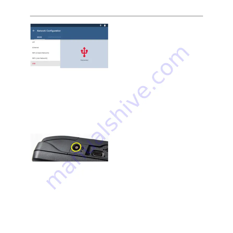
Fig. 2.7 


Once the driver is installed, the networking status 
in the Network Configuration screen of the gauge 

will update to say “Connected.”


TEC software installed on the laptop computer will now be able to detect the DG-1000 and create a 
communication link. 

2.3.2


Wireless connection of the DG-1000 (WiFi) 

The DG-

1000’s built

-in WiFi module can be configured to create and broadcast a wireless network that 

can be connected to directly from a computer or mobile device (

 Chap. 2.3.2.1). The DG-1000 can 

join an existing wireless network (

 Chap. 2.3.2.2). 

2.3.2.1


Connection via the integrated WiFi module 


Fig. 2.8 


Turn on the DG-1000 pressure gauge by pressing 
and holding the power button for approx. 3 
seconds until the green power indicator light 
turns on, and wait until the DG-1000 is booted.  

The bootup process may take some seconds to 
complete, and the gauge is ready to be used 
when the home screen appears (shown below). 

Summary of Contents for BlowerDoor Standard

Page 1: ...Minneapolis BlowerDoor Model 4 1 with DG 1000 TECTITE Express version 5 1 BlowerDoor Standard...

Page 2: ...Eldagsen Phone 49 5044 975 40 Fax 49 5044 975 44 info blowerdoor com www blowerdoor com All rights reserved This Reference Guide including all illustrations is copyright protected Any use beyond the s...

Page 3: ...TECTITE Express 12 2 3 Installing the DG 1000 13 2 3 1 Installing the DG 1000 using USB C port 15 2 3 2 Wireless connection of the DG 1000 WiFi 17 2 3 2 1 Connection via the integrated WiFi module 17...

Page 4: ...top 44 4 5 4 Connecting the tubing to the DG 1000 45 4 6 Overview of the Negative Pressure Test and Positive Pressure Test 46 4 6 1 Overview of the negative pressure test depressurization measurement...

Page 5: ...Data 73 A 1 Minneapolis BlowerDoor Measuring Fan Model 4 1 73 A 2 Digital Pressure Gauge DG 1000 74 A 3 Software TECTITE Express 75 A 4 BlowerDoor Mounting Frame and BlowerDoor Panel 76 Appendix B Cal...

Page 6: ...tandard Testing the flow sensor 84 Cleaning the fan 84 B 3 Fan Speed Controller 85 Replacing the fuse 85 Appendix C Expansion Capabilities of the BlowerDoor Measurement System 88 Our Service Offer 94...

Page 7: ...istributor Make sure that there is sufficient clearance between the tips of the fan blades and the fan housing Examine the motor for excessive dust build up Use a vacuum to remove the dust or blow out...

Page 8: ...Once properly installed the mounting frame can easily withstand pressures of up to 100 Pa Keep the area around the fan clear of obstacles Maintain a clearance of 1 to 2 meters around the fan so that...

Page 9: ...r 2 BlowerDoor panel standard size 7 Fan control cable connection DG 1000 3 BlowerDoor mounting frame standard size controller 4 Set of tubes connection fan DG 1000 8 Set of tubes capture outside pres...

Page 10: ...speed controller 3 BlowerDoor mounting frame standard size 8 Fan control cable connection DG 1000 4 USB data cable DG 1000 laptop controller 5 Set of tubes connection fan DG 1000 9 Set of tubes captur...

Page 11: ...sing airtightness respectively air permeability in new buildings and comparing the results with legal requirements such as the Energy Conservation Act Locating leaks during construction of single fami...

Page 12: ...e connected computer is required to comply with IEC 60950 1 or equivalent standards on data port electrical safety isolation 2 2 Installing TECTITE Express TECTITE Express is a steering program With i...

Page 13: ...in Chap 5 2 3 Installing the DG 1000 There are different options for connecting your DG 1000 gauge to your laptop computer to create the two way communication link needed for automated testing with T...

Page 14: ...f multiple gauges that can connect to a computer The USB C port on the DG 1000 can be used to create a communication link between the differential pressure gauge and a Windows computer using a USB dat...

Page 15: ...er Make sure the computer is connected to the internet Windows Update on the computer must be configured to allow downloading and installation of driver software Fig 2 2 Turn on the DG 1000 pressure g...

Page 16: ...om the Network Configuration options The networking status in the Network Configuration screen will show Not Connected Fig 2 6 Connect the DG 1000 to your laptop via the USB C interface using a USB da...

Page 17: ...module can be configured to create and broadcast a wireless network that can be connected to directly from a computer or mobile device Chap 2 3 2 1 The DG 1000 can join an existing wireless network C...

Page 18: ...ouch Settings on the home screen Fig 2 10 Select Network Configuration Fig 2 11 Select WiFi Create Network from the Network Configuration options The DG 1000 will begin broadcasting a secured wireless...

Page 19: ...the WiFi network to be visible on your laptop TEC software installed on the computer or mobile device should now be able to detect the gauge and create a communication link The DG 1000 s wireless net...

Page 20: ...reless network using one of these methods The DG 1000 can search for nearby wireless networks and populate a list so one can be selected and joined A wireless network name SSID can be manually typed i...

Page 21: ...d January 2022 21 Fig 2 17 To enable WiFi Join Network touch Settings on the home screen Fig 2 18 Select Network Configuration Fig 2 19 Select WiFi Join Network Then touch Select WiFi Network The DG 1...

Page 22: ...se the keypad provided to enter the password Then touch Connect Fig 2 22 Notes Should the password require a character that is not part of the keyboard on the gauge connect a keyboard using the USB A...

Page 23: ...1000 was able to connect Once the DG 1000 joins a wireless network the gauge can be accessed using TEC software if the computer or mobile device running the software is also connected to the same net...

Page 24: ...utton for approx 3 seconds until the green power indicator light turns on and wait until the DG 1000 is booted The bootup process may take some seconds to complete and the gauge is ready to be used wh...

Page 25: ...to show Connected If the status continues to show Not Connected after two minutes make sure the cables have been installed correctly and that the router is powered and running DHCP Server Connect the...

Page 26: ...whether the DG 1000 is recognized by your laptop Turn on your DG 1000 and connect to laptop computer Chap 2 3 1 to 2 3 3 Start the TECTITE Express software for your check Alternative 1 Go to the File...

Page 27: ...button Fig 2 31 Once the Scan window is open clicking on Start Scan will provide a list of all installed communication ports on your computer The scan will also show all BlowerDoor Devices that are c...

Page 28: ...in the COM Port Selection window will allow TECTITE Express to automatically search for BlowerDoor devices on all available communication ports on your computer If you are unsure which COM Port to use...

Page 29: ...bag contains the red BlowerDoor panel the fan speed controller hoses the fan cap the reference guide the calibration certificates and if chosen a leak locating device 3 1 Measuring fan and speed cont...

Page 30: ...3 2 DG 1000 Fig 3 4 DG 1000 Differential pressure and flow gauge DG 1000 for automatic semi automatic and manual BlowerDoor measurement in padded bag with two lithium Ion batteries rechargeable insta...

Page 31: ...nected to a laptop the DG 1000 automatically controls the fan You can maintain a constant building pressure for leakage detection and you can also conduct an automated as well as Compartment for recha...

Page 32: ...n 25 Pa 75 Pa 0 Pa and 0 Pa are preset You can also conduct manual measurements and read the differential pressures from the gauge s display The gauge regularly zeroes out the sensors you will hear a...

Page 33: ...the external door of a large room is a good option Air must flow through the fan unobstructed A minimum clearance of 1 5 meters must be maintained around the fan see Appendix B Fig 4 1 The BlowerDoor...

Page 34: ...el see Fig 4 7 below 4 2 Installing the mounting frame and panel The mounting frame and panel are installed from inside the building The four external braces of mounting frame are laid on the ground s...

Page 35: ...osely fit the dimensions of the door frame leave about a finger s width on all sides Slide the frame into the door opening Re adjust the frame height and width to the door opening by loosening the kno...

Page 36: ...g up The Velcro straps on the panel should also face up Loosely fold the panel around the frame and secure it with the Velcro straps Fig 4 7 Before installing the fan into the panel opening attach the...

Page 37: ...against the top brace Loosen the adjustment knob of one of the vertical braces Slide the braces apart and press them firmly into the door opening Once the height is fixed retighten the adjustment kno...

Page 38: ...tabilize the frame To install the cross bars release the adjustment knobs on the bars slide the cross bar halves apart insert the ends of the cross bars into the slots on the vertical frame braces tig...

Page 39: ...collar in the panel so that the flow rings are facing into the room The rubber pad on the bottom of the fan is set on the lower frame brace The elastic collar should fit snugly around the fan Fig 4 13...

Page 40: ...ring The building envelope is more airtight than expected and you will have to insert a smaller ring If the aperture of the flow ring chosen is too small you will not even reach the desired building p...

Page 41: ...e connects to ring D Fig 4 18 Putting on the fan cover Seal off the fan by installing the nylon fan cover over the fan The fan is sealed in order to measure the building baseline pressure during the a...

Page 42: ...el Fig 4 21 Connect one end of the green tubing to the patch at the bottom right corner of the panel Outside the building the clear tubing should have been connected to the same patch Fig 4 22 For det...

Page 43: ...lue on the fan electrical box 4 5 Connecting the Pressure Gauge DG 1000 4 5 1 Power supply for the DG 1000 Fig 4 24 The DG 1000 uses two lithium ion batteries that are rechargeable and replaceable The...

Page 44: ...storing the pressure gauge in its pocket remove all connected cables 4 5 3 Connecting the DG 1000 to a laptop In order to conduct automated measurements with a laptop and TECTITE Express connect the D...

Page 45: ...ressure Channel B Fan Pressure Differential flow INPUT red tubing fan pressure REF blue tubing fan reference pressure Fig 4 29 If there is air turbulence near the gauge perhaps due to location e g a n...

Page 46: ...gs point inward and air is sucked out of the building Fig 4 30 If flow ring D or E is used the red tubing should be connected to ring D instead of to the fan Channel A Building Pressure Green tubing c...

Page 47: ...rings point outwards and air is sucked into the building The tubing connections do not change Optional If you encounter strong pressure fluctuations while recording the pressurization series connect a...

Page 48: ...you to take one point measurements Fig 5 1 TECTITE Express offers detailed help for all windows i e warning message windows The Help button always appears in the upper right of the window Familiarity...

Page 49: ...in the menu bar Fig 5 5 Test Standard Selection Use this window to select the Measuring Standard EN ISO 9972 or EN 13829 The ISO is preselected Check marking the box Set as Defaults for New Tests will...

Page 50: ...mation window Enter all data relevant to the test in this window dates tester customer building address and building data Fig 5 8 Comments window This window is for additional notes such as placement...

Page 51: ...andards if necessary Note An increase in the Samples per station measuring points per pressure differential to for example 300 will improve accuracy since more values are used to determine the mean va...

Page 52: ...his window controls the automated measurement including the method of testing positive or negative pressure A green status bar indicates that the DG 1000 has been installed correctly and is recognized...

Page 53: ...ressure see Chap 5 2 5 1 Leakage Detection at Constant Negative Pressure with TECTITE Express For an initial assessment of airtightness and for locating leaks during a walk through generate a constant...

Page 54: ...se Pressure 50 Pa Fig 5 16 Test graph window Display Large Meters Building pressure current flow rate and the estimated air change rate n50 at 50 Pa are shown in the large display window If the flow r...

Page 55: ...raph window Now start the automated test by hitting Start Test The software will interactively guide you through the test procedure Fig 5 18 Temperature and Barometric Pressure Entry Temperature indoo...

Page 56: ...taken directly after each other TECTITE Express shows both curves in one diagram Fig 5 20 Data point selection and deletion Individual data points can be reviewed and permanently deleted from the gra...

Page 57: ...ts The results are shown with the preset reference pressure of 50 Pa If needed the reference pressure can be changed according to country specific requirements Fig 5 22 Saving viewing and printing res...

Page 58: ...the building or a combination of the three points the automated BlowerDoor Test in TECTITE Express maybe don t work proper Then use the Semi Automated Test Fig 5 23 Test settings window Select Semi A...

Page 59: ...y with your hand Then wait until the cursor is more or less stable It takes some time to attain stable pressure do not make any unnecessary adjustments while waiting If the cursor is stable then press...

Page 60: ...ts including a Detailed Test Report and a Test Graph Fig 6 1 Report printing and previewing options are available by clicking on File in the Main Menu The printing and preview functions within TECTITE...

Page 61: ...rt BlowerDoor Standard January 2022 61 6 1 Detailed Test Report The detailed Test Report contains a complete listing of the building data test data test results as well as any comments input into the...

Page 62: ...timate the relationship between air leakage and building pressure 6 3 Creating a PDF File of the Test Reports TECTITE Express makes it easy to create a PDF file of any of the reports Simply choose the...

Page 63: ...To access the Business Info window click on Options in the Main Menu and then select Business Info Fig 6 5 Information entered in the Business Info window is saved as part of the data files To insert...

Page 64: ...ell as at a customer defined pressure differential with BlowerDoor system including DG 1000 without laptop Remote controlling the DG 1000 via TECTITE Express or via a mobile device with the app TEG Ga...

Page 65: ...o allows you to quickly assess the airtightness of existing buildings No measurement according to European Standard The one point measurement is no substitute for a measurement according to standard E...

Page 66: ...nnel B Q signifies flow In this mode Channel A measures the building pressure differential Channel B displays the calculated airflow at 50 Pa The magnitude of this airflow depends on the size of the f...

Page 67: ...led flow ring on the DG 1000 The current fan model and flow ring appears at the bottom of the right cell of the display Model 4 220 V fan and open fan configuration is preselected Use the arrow to ret...

Page 68: ...get pressure of 50 Pa is preset Fig 7 9 Activating Cruise Control on the DG 1000 Press the Play icon to the start Cruise function The fan is automatically adjusted to the selected building pressure di...

Page 69: ...d a pop up will appear at the bottom of the screen that says Cruise canceled Touch the red stop icon in the bottom right corner of the screen to stop the fan When the fan is stopped a pop up will appe...

Page 70: ...differential pressure Pressure Pa Actual air flow rate Q m h Calculated airflow rate at 25 Pa 50 Pa 75 Pa Q xx Pa m h Air change rate n50 in order to display it is required to enter the building volu...

Page 71: ...f a test pressure of 50 Pa can t be reached you will hear a beeping sound from the DG 1000 End the test and install the next largest flow ring on the fan Set the new flow ring configuration on the DG...

Page 72: ...setting on the gauge and choose the 5 or 10 second or Long term averaging period The default period is 1 second To change touch the small gray triangle next to 1 second pre set measurement time inter...

Page 73: ...ichever is greater meets EN ISO 9972 2015 EN 13829 FD P50 784 CIBSE TM23 ATTMA TS 1 ASTM E779 10 ASTM E1554 07 CGSB 149 10 M86 RESNET 2012 NFPA 2001 Electrical Input 220 240 V 50 Hz 3 7 A 1 Ph Fan Ove...

Page 74: ...d NFPA 2001 RESNET and US ACE Recommended Calibration Interval two years according to the manufacturer s specification Units of Measure Channel A differential pressure in Pa or in H2O Channel B differ...

Page 75: ...W x H 177 x 107 x 36 mm Weight approx 445 g Compatibility Compatible with all TEC devices Stand alone Cruise control for one point measurement Automatically maintains a building pressure differential...

Page 76: ...ting Frame and BlowerDoor Panel BlowerDoor Mounting Frame standard size adjustable Material Extruded aluminum Minimum and maximum width 0 71 m to 1 14 m Minimum and maximum height 1 32 m to 2 43 m Sea...

Page 77: ...rt and into a router with internet connection Set the selected connection type in the DG 1000 menu Settings Network configuration For a wireless connection to the Internet select the menu Settings WiF...

Page 78: ...and recorded The calibration is then adjusted and the gauge is retested If damage is suspected have the DG 1000 inspected by our service Safety warnings and troubleshooting information Do not operate...

Page 79: ...om the battery leaks out and makes contact with skin wash with soap and water The fluid may cause irritation If that happens please see a doctor immediately Do not expose the batteries to extreme heat...

Page 80: ...ors do not belong to household waste but must be disposed of separately Touch screen use and care A screen protector is included with the DG 1000 Replacement screen protectors can be purchased from Bl...

Page 81: ...s C n Open fan flow m h 745 4 fan pressure in Pa 0 4848 Ring A installed flow m h 273 2 fan pressure in Pa 0 4952 Ring B installed flow m h 81 69 fan pressure in Pa 0 4968 Ring C installed flow m h 19...

Page 82: ...ur office for more information With the exception of damage the fan should retain its factory set calibration settings between the recommended calibrations Damage may include damage to the flow sensor...

Page 83: ...ee from dust deposit Testing the motor position To test the motor position remove all rings Lay a straight edge upright over the fan housing Use a ruler or a yard stick to measure the distance between...

Page 84: ...l tubing on the back of the sensor Temporarily seal them e g with masking tape Attach a piece of tubing to the connection on the electrical box marked in red near the handle Next suck on the open end...

Page 85: ...as possible B 3 Fan Speed Controller If the Model 4 Bower Door fan stops running or fails to respond to speed commands Verify that the fan speed controller is turned ON Verify that the fan speed cont...

Page 86: ...ilter See Image below for details Firmly grasp the black handle of the fuse holder and pull out the old fuse Carefully slip the old fuse out of the black handle Insert the new fuse into the black hand...

Page 87: ...andard January 2022 87 Verify Operation Reconnect the controller power cord to the AC power mains outlet Turn ON the controller Power Switch Adjust speed control knob from minimum to half speed and ve...

Page 88: ...ipleFan 2 fans WiFi connection 1 BlowerDoor fan 2 pcs 5 Digital pressure gauge DG 1000 2 pcs 2 BlowerDoor panel standard size with 2 6 Fan speed controller 2 pcs openings 7 Communication jack 3 Blower...

Page 89: ...s 5 Digital pressure gauge DG 1000 2 pcs 2 BlowerDoor panel standard size with 3 6 Fan speed controller 3 pcs openings 7 Communication jack 3 BlowerDoor mounting frame standard size 8 Cable with jack...

Page 90: ...standard size with 3 connection router laptop openings 7 Digital pressure gauge DG 1000 2 pcs 3 BlowerDoor mounting frame standard size 8 Fan speed controller 3 pcs additional upper middle cross bar...

Page 91: ...6 Communication jack 2 BlowerDoor panel standard size 7 Digital pressure gauge DG 1000 2 pcs 3 BlowerDoor mounting frame standard size 2 pcs 8 Fan speed controller 3 pcs 4 BlowerDoor panel standard si...

Page 92: ...ure gauge DG 1000 4 pcs 2 BlowerDoor panel standard size with 3 6 Fan speed controller 6 pcs openings 2 pcs 7 Communication jack 2 pcs 3 BlowerDoor mounting frame standard size 8 Cable with jack plugs...

Page 93: ...Appendix C Expansion Capabilities of the BlowerDoor Measurement System BlowerDoor Standard January 2022 93 Set up possibility of BlowerDoor MultipleFan 12 fans Fig 9 6...

Page 94: ...kkS calibration which are conducted according to a standard defined by the German accreditation body Deutsche Akkreditierungsstelle GmbH DAkkS BlowerDoor GmbH offers calibration of fans and of pressur...

Page 95: ...Upon request we support BlowerDoor testing teams with professional printable files on BlowerDoor measurements free of charge The material will feature your own contact data and company logo View a sam...

Page 96: ...the repaired measuring device customers shall send the measuring device loaned to them back to BlowerDoor GmbH at their own expense immediately The costs as well as the risk of loss or damage on the...

Page 97: ...ringe Eldagsen Germany Tel 49 0 5044 975 40 shall be entitled to accept claims under guarantee Customers shall send the faulty measuring device or component to BlowerDoor GmbH BlowerDoor GmbH shall be...

Page 98: ...Door Model 4 1 conforms to the council directives and harmonized standard requirements for Electrical Equipment for Measurement Control and Laboratory Use EC Low Voltage Directive 2006 95 EC EN 61010...

Page 99: ...ive 2006 95 EC TUV SUD America Minneapolis MN EC EMC Directive 2004 108 EC International Certification Services Glencoe MN European Representative BlowerDoor GmbH MessSysteme f r Luftdichtheit Zum Ene...

Page 100: ...rd requirements for Electrical Equipment for Measurement Control and Laboratory Use EC RTTE 1999 EC ETSI EN 301 489 17 V2 2 1 2012 referencing EN 301 489 1 V1 9 2 2011 EN 60950 1 2006 A12 2011 EC Low...

Page 101: ...age Directive 2014 35 EU TUV SUD America Minneapolis MN EC EMC Directive 2004 108 EC TUV SUD America Minneapolis MN European Representative BlowerDoor GmbH MessSysteme f r Luftdichtheit Zum Energie un...

Page 102: ...rotective charge EUR 18 BlowerDoor GmbH 2022 BlowerDoor GmbH MessSysteme f r Luftdichtheit Zum Energie und Umweltzentrum 1 D 31832 Springe Eldagsen Phone 49 5044 975 40 Fax 49 5044 975 44 info blowerd...

Reviews: