4
5
11. Position the block of packing wood at the slave column end
of the base frame, as per Step 7, and stand up the column as per
Step 8. Measure the height of both the drive and slave column
carriages and adjust by rotating the chain sprocket on the slave
column until they are the same height. Move the slave column
toward the drive column about 80 mm and fit the chain to the
sprocket. Move the column back again until the chain is tight,
then remove the packing wood as per Step 9.
12. Bolt the slave column down as per Step 10. Measure the
lean on the drive column and the slave column using a plumb
line. Each column should lean outwards between 14 and 26 mm
from top to bottom. Sideways lean should be a maximum of 5
mm off vertical.
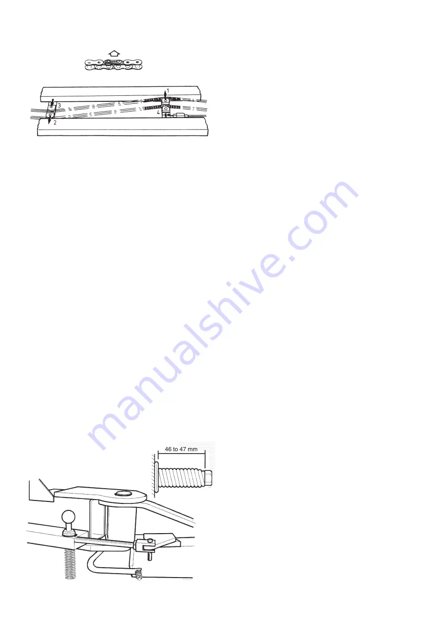
13. Tighten the chain by adjusting the four chain guides in the
order shown in Fig.2 until the spring on guide No.4 is just fully
compressed.
Note: to allow the spring to compress, the square locking plate
at the end of the spring must be held vertical by pushing the
top of the plate towards the No.4 chain, guide. Do not over-
tighten the chain, as this will shorten the life of the chain and
guides.
14. Fit the chain limit switch into position, with the limit switch
roller pushing on the plate beside the chain tension spring.
Retain with two M4 x 25 mm long screws. Check the limit switch
roller can still be moved 2 mm to 4 mm clear of the plate before
running out of travel.
15. Apply a smear of grease in the lifting arm pivot holes and the
carriage pivot holes. Fit the lifting arms to the carriages. Fit the
pivot pins and retain with a circlip top and bottom as per Fig.3.
Check the circlips are fully in their grooves.
16. Fit the footguards to the lifting arms as per Fig.3 and tighten
the bolts until the spring is compressed to a length of 46 to 47 mm.
17. Fit the tool trays to 2 of the lifting arms with the M6 x 16
screws and Ø19 x 2 mm thick flat washers.
Do the screws up snug tight only, (over tightening will distort
the tray). Check the arms slide in and out freely.
18. Place a lifting pad in the hexagonal hole in each lifting arm.
19. Fit the armlock devices to the carriages and arms as per
Fig.3. Check that the circlips are fully in their grooves and the
Nyloc nut is tightened up fully on the M8 x 55 mm long cap
screw. Lift up on each black knob and check each arm moves
freely through the full arc. Release the knob and check the arm
is locked.
20. Fit the cover over the bottom limit switch and tee piece
using two M6 x 10 mm long socket head cap screws. Fit the
motor cover over the vee belts and secure with the M4 x10 mm
long screw and large flat washer.
21. Connect the power supply from the mains isolator switch,
adjacent to the hoist, to the control box on the drive column.
Use the cable gland supplied in the control box to seal the cable
entry in the control box.
Note: This must be done by a qualified electrician.
For a three phase hoist, use 3-core plus earth, 7- strand, 2.5 mm²
copper cable and connect the three active wires to the terminal
strip in the control box. Connect the earth (green) wire to the
earth terminal.
For a single phase hoist, use 2-core plus earth, 7- strand, 4 mm²
copper cable. Connect the active (brown) wire to terminal 1, L1,
on the contactor. (marked K1M). Connect the neutral (blue) wire
to terminal 5, L3 on the contactor. Connect the earth (green)
wire to the earth terminal.
22. Switch on the power to the hoist. Turn the operating switch
to up. The hoist should go up. If it goes down, stop immediately
and turn off the mains isolator, for a three phase hoist, swap two
of the power supply wires at the terminal strip in the control
box. For a single phase hoist, check that the active and neutral
wires have been connected to the correct terminals. Switch the
power back on.
23. Drive the hoist fully up to check operation of the top limit
switch. Drive hoist fully down to check operation of the bottom
limit switch. Swing the four lifting arms in and out with the
lifting pads screwed fully down. If the arms hit the floor in any
position, adjust the arm on the bottom limit switch so the lifting
arms clear. Loosen the chain and try operating the hoist –it must
not operate! Retighten the chain as per Step 13.
24. Apply a liberal amount of oil to the chain and to the slideway
of the spring-loaded chain roller. Fit the drive on ramp and bolt
it down with the M8 x 16 screws and flat washers.
25. Drive the hoist up 1 m clear of the floor. Fit a funnel through
the hole in the front blind in the drive column. Pour in a half a
litre of the recommended extreme pressure oil (supplied). Pour
the other half litre into the slave column.
Note: 1⁄2 litre of oil will half-fill the oil reservoir in each column.
Do not have the reservoirs more than half full as the excess oil
will be quickly lost.
26. Drive the hoist up and down four or five times to lubricate
the lifting screws.
The hoist is now ready for operation.
Fig.2
IMPORTANT:
Link must be seen from
the top when installed.
FIG. 3


