EU – 401N User’s manual v 1.1.3
-
12
-
Example:
If the gear coefficient value is 3, each 3°C difference between the tank temperature and the collector
temperature results in 10% increase in pump speed.
The table below contains examples of the coefficient values and its results.
Gear coefficient 3 Gear coefficient 4 Gear coefficient 5 Gear coefficient 6
Pump
working
revolutions
Δ
value
(collector temp.
– tank temp.)
Δ3
Δ4
Δ5
Δ6
10%
Δ6
Δ8
Δ10
Δ12
20%
Δ9
Δ12
Δ15
Δ18
30%
Δ12
Δ16
Δ20
Δ24
40%
Δ15
Δ20
Δ25
Δ30
50%
IV.c.6)
Solar pump work minimum
This parameter is available only if regulated revolutions option is selected. Using this setting the user
should define the pump minimum initial speed.
IV.c.7)
Solar pump work maximum
This parameter is available only if regulated revolutions option is selected. Using this setting the user
should define the pump maximum operating speed (%).
IV.c.8)
Installation sampling
This function enables the user to activate or deactivate circulation sampling, aimed at updating the
temperature reading, by activating the collector pump for a short period of time (when standard
conditions of pump activation are not met). Sampling forces short-time activation of the pump after
the collector temperature increase of at least 3°C.
IV.c.9)
Control revolutions
These parameters enable the user to choose the type of PWM pump used:
•
Increase
It concerns PWM pump whose speed increases when the signal increases.
•
Decrease
It concerns PWM pump whose speed decreases when the signal increases.
IV.d)
Peripherals
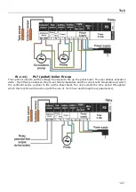
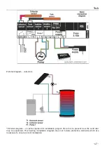
The user may connect and configure the settings of an additional device. If there is no additional device,
the user should select NONE (deactivate). Additional devices to choose from and examples of
connections supporting all available installation schemes are presented below. In the case of schemes
12 and 14 it is not possible to connect an additional device - the function is unavailable.
IV.c.10)
Circulating pump
Once this device is selected, the user should adjust
operation time
and
pause time
of the pump during
its activity. Next, the user should define the hours of pump operation using
From hour
and
Through
hour
functions. Entering the same times (from – through) will result in the device being active
throughout the whole day.


