background image

Tech 

15

 - 


IV.e.3)


Type of medium


The user chooses the agent used:  ethylene glycol, propylene glycol or water.


IV.e.4)


Glycol solution


The user specifies glycol concentration in water (given in percent.


IV.e.5)


Calibration


This  function  allows  the  user  to  calibrate  the  temperature  difference  between  the  sensors.  The 
temperature is measured in the place where the temperature sensor is installed. Deviations may occur 
in the flow and temperature measurement at the tank return. The manufacturer does not recommend 
changing this setting.


IV.f) 


Alarm sound


This function enables the user to activate/deactivate the sound signal after an alarm occurs.


IV.g) 


Factory settings


The controller is pre-configured for operation. However, the settings should be customized to the user's 
needs. Return to factory settings is possible at any time. Once the factory settings option is activated, 
all  customized  settings  of  the  solar  installation  controller  (saved  in  the  user's  menu)  are  lost  and 
replaced with the manufacturer's settings. Then, the parameters may be customized anew. Return to 
factory settings results in activating the default installation scheme. 


IV.h) 


Edit service code


It is possible to edit service menu code. Go to this submenu, enter the code and confirm the settings. 


V. Protections


In order to  ensure safe and failure-free  operation, the controller is  equipped with a range of 

protections.


1. Sensor protection.


If one of the sensors is damaged, an acoustic signal is activated and the following symbol 

will 

appear  on  the  right  hand  side  of  the  display.  An  additional  icon  informing  the  user  which  sensor  is 
disconnected or damaged will flash in the place of its temperature. In order to deactivate the alarm 
signal in case of error, press

 EXIT 

button.


2. Protection against collector overheating.


If  the  maximum  (alarm)  temperature  is  reached,  the  regulator  switches  to  the  so-called

  collector 

overheat mode

 and the display shows a corresponding symbol 

. The pump is enabled in order 

to  cool  down  the  collector  until  the 

maximum  tank  temperature

  is  reached  or  until  the  collector 

temperature drops by the value of the 

alarm hysteresis 

(see: 

SERVICE MENU > Solar Collector> Alarm 

Hysteresis

) In the case of two tanks, both of them are used to cool down the overheated collector (at 

the same time or one by one, depending on the operation algorithm setting).


3. Heat tank protection.


In the event of collector overheating, each tank may be heated to no more than the pre-set maximum 
safe temperature. After reaching this temperature, the pump of a given tank is disabled (in system 
configuration with two tanks and a valve, the circulation is switched to the second tank).  


4. Fuse.


The regulator is equipped with a WT 3.15A tube fuse-link protecting the network.


Summary of Contents for EU-401N PWM

Page 1: ...Tech 1 EU 401N PWM...

Page 2: ...led by a qualified electrician Before starting the controller the user shoud measure earthing resistance of the electric motors as well as the insulation resistance of the cables The regulator should...

Page 3: ...done directly from the controller An additional signal relay is necessary in order to control the heater The controller offers PWM pump control option enabling the user to adjust its rotational speed...

Page 4: ...icons Active operation mode icon Icon of active additional device peripherals Automatic operation mode Circulating pump Collector defrost mode Pellet boiler fire up voltage free signal Holiday mode H...

Page 5: ...ature is reached to define the pre set temperature go to SERVICE MENU Accumulation tank Pre set temperature or until the difference between collector and tank temperature reaches solar pump deactivati...

Page 6: ...raising the temperature of water in the tank to the required disinfection temperature read from the upper sensor of the tank in the case of using an optional sensor the user should make sure that it...

Page 7: ...nd connecting an additional controlling module ST 65 which is not included in the standard controller set GSM module is an optional device which cooperating with the controller enables the user remote...

Page 8: ...sion of the controller menu V d Information Once this option has been selected the display shows the controller manufacturer s logo and current software version V e Factory settings This function is u...

Page 9: ...ure Pumps Regulated revolutions Maximum collector temperature Solar pump deactivation delta Solar pump activation delta Gear coefficient Solar pump working minimum Solar pump working maximum Installat...

Page 10: ...tank until the maximum temperature is reached To prevent the accumulation of too hot water in the tank Cooling to pre set temperature function should be activated Once activated when the collector te...

Page 11: ...etting the user declares the value of the collector maximum alarm temperature at which the pump may be damaged This temperature should be adjusted according to the collector technical specification Du...

Page 12: ...collector pump for a short period of time when standard conditions of pump activation are not met Sampling forces short time activation of the pump after the collector temperature increase of at leas...

Page 13: ...r The user defines activation delta the difference between the pre set tank temperature and the current tank temperature at which the controller sends a signal to fire up the boiler Next the user sele...

Page 14: ...ime period which means all the time Sensor 4 is required for it to operate correctly it should be installed in the external DHW tank This function will not operate in the installation scheme which use...

Page 15: ...rotections In order to ensure safe and failure free operation the controller is equipped with a range of protections 1 Sensor protection If one of the sensors is damaged an acoustic signal is activate...

Page 16: ...01N controller should be checked for condition of its cables The user should also check if the controller is properly mounted and clean it if dusty or dirty Power supply 230V 10 50Hz Power consumption...

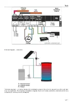
Page 17: ...ictorial diagram it cannot replace CH installation project Its aim is to present how the controller may be expanded This heating installation diagram does not include protective elements which are nec...

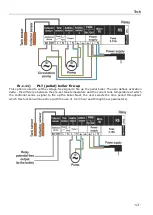
Page 18: ...EU 401N User s manual v 1 1 3 18 PWM pump connection scheme...

Page 19: ...o electromagnetic compatibility EU OJ L 96 of 29 03 2014 p 79 Directive 2009 125 EC establishing a framework for the setting of ecodesign requirements for energy related products as well as the regula...

Page 20: ...EU 401N User s manual v 1 1 3 20...

Reviews: