EU – 401N User’s manual v 1.1.3
-
4
-
III. User menu
III.a)
Home page
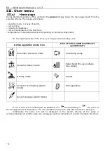
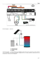
During standard operation of the controller, the
graphic
display shows the main page. Apart from the
selected scheme, the display also shows:
- operation mode (or type of alarm),
- current time,
- collector temperature
- current temperature of the heat tank
- temperature of all additional sensors depending on selected configuration
On the right-hand side of the screen you may see the following icons:
Active operation mode icon
Icon of active additional device
(peripherals)
Automatic operation mode
Circulating pump
Collector defrost mode
Pellet boiler fire-up (voltage-
free signal)
Holiday mode
Heater
Collector overheating (alarm
mode)
Anti-legionella
Sensor damage (alarm mode)
If one of the sensors is damaged, an additional icon
will be flashing in
the place of
the damaged sensor temperature. The icon indicates which sensor was disconnected or damaged.
Additionally, the pump icon will be displayed on the system scheme (if the pump is
working/rotating) or/and the valve icon will appear (with an indication of current circulation direction).


