11
3.1.
SCHEMAT INSTALACJI
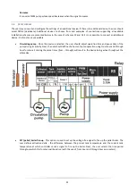
To ensure
effective operation of the solar heating system, it is necessary to select proper installation scheme (SERVICE
MENU > INSTALLATION SCHEME) and configure additional options for the selected scheme.
NOTE
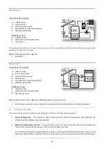
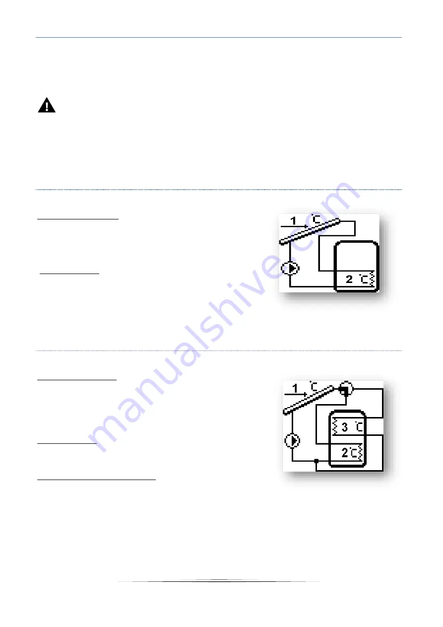
While selecting an installation scheme, in the place of the sensor temperature the screen displays the sensor
number. Follow these numbers while connecting the sensors in proper places (order from left to right):
(1) – collector sensor (PT1000),
(2) – tank sensor (PT1000),
(3)– additional sensor 1 (PT1000),
(4) – additional sensor 2 (PT1000).
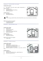
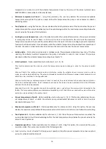
SCHEME 1/17
–
BASIC
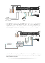
Installation 1/17 supports:
➔
collector pump,
➔
accumulation tank,
➔
one direction of collector positioning,
➔
additional peripherals.
Installation sensors:
➔
collector sensor,
➔
accumulation tank sensor.
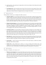
SCHEME 2/17
–
ONE TANK
–
SEQUENCE
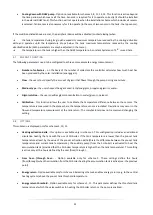
Installation 2/17 supports:
➔
collector pump,
➔
top-bottom switching valve,
➔
accumulation tank with lower and upper circuit
➔
one direction of collector positioning,
➔
additional peripherals.
Installation sensors:
➔
collector sensor,
➔
two sensors of the accumulation tank - upper one and lower one.
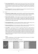
Additional parameters to be configured:
o
valve hysteresis
o
oscillation charging
o
oscillation pause
o
maximum heating time Z2


