14
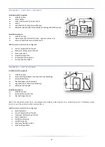
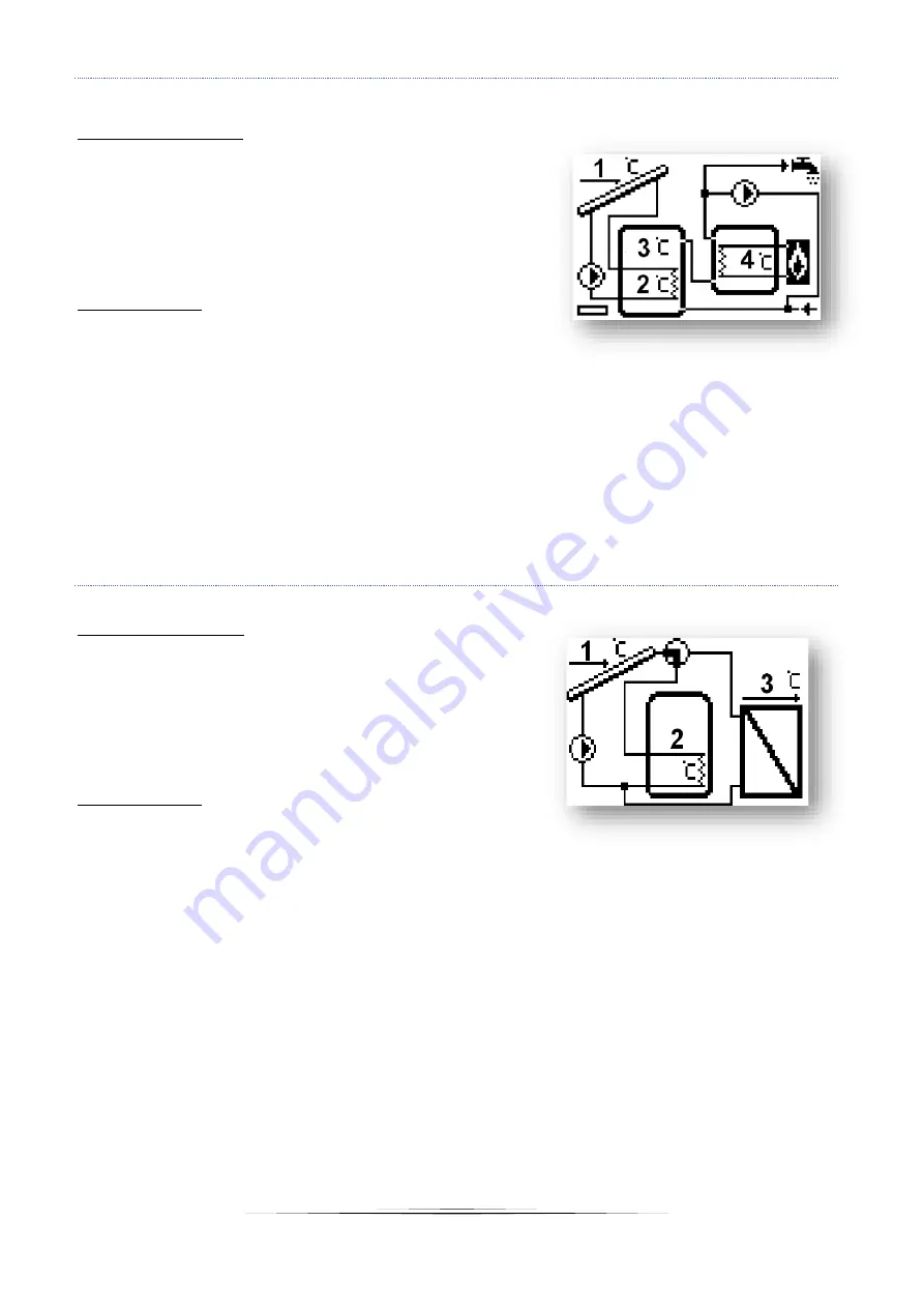
SCHEME 8/17
–
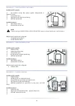
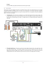
TWO TANKS
–
SEQUENCE
Installation 8/17 supports:
➔
collector pump,
➔
tank 2 pump,
➔
tank 1 with lower and upper circuit
➔
tank 2,
➔
one direction of collector positioning,
➔
additional peripherals (no possibility of cooling with DHW pump)
Installation sensors:
➔
collector sensor,
➔
two sensors of accumulation tank - upper and lower one
➔
sensor of additional accumulation tank.
Additional parameters to be configured:
•
Pre-set temperature of tank 2
•
Maximum temperature of tank 2
•
Tank hysteresis 2
•
Operation algorithm
•
Pump deactivation delta 2
•
Pump activation delta 2
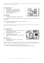
SCHEME 9/17
–
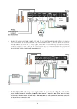
HEAT EXCHANGER
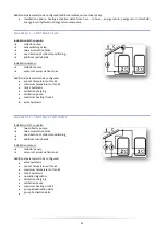
Installation 9/17 supports:
➔
collector pump,
➔
valve switching between the tank and heat exchanger
➔
accumulation tank,
➔
heat exchanger (heat receiver),
➔
one direction of collector positioning,
➔
additional peripherals.
Installation sensors:
➔
collector sensor,
➔
accumulation tank sensor.
➔
heat exchanger sensor.
Apart from the accumulation tank, this system also includes a heat receiver (e.g. swimming pool or CH system) whose
task is to emit the heat rather than accumulate it
.
Additional parameters to be configured:
•
valve hysteresis
•
pre-set temperature of tank 2
•
maximum temperature of tank 2
•
tank 2 hysteresis
•
oscillation charging
•
oscillation pause
•
maximum heating time Z2
•
tank heating priority


