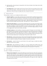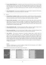
16
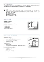
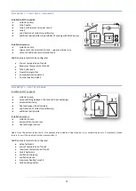
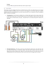
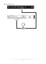
SCHEME 12/17
–
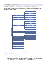
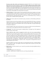
TWO COLLECTORS, TWO PUMPS, TANK AND ADDITIONAL HEAT RECEIVER
Installation 12/17 supports:
➔
two collector pumps (operating independently in separate
circuits),
➔
accumulation tank with lower circuit,
➔
two directions of collector positioning,
➔
additional heat receiver,
➔
valve switching between main circuit and additional receiver
Installation sensors:
➔
two collector sensors,
➔
accumulation tank sensor,
➔
sensor of additional receiver
NOTE
No possibility of connecting and selecting an additional device -
Peripherals
submenu is not available in the
service menu. Switching valve controlling the additional receiver is connected in the place of peripheral device.
Additional parameters to be configured:
•
Pump 2 deactivation delta
•
Pump 2 activation delta 2
•
Heat receiver : maximum receiver temperature, heat receiver hysteresis
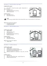
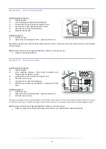
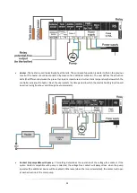
SCHEME 13/17
–
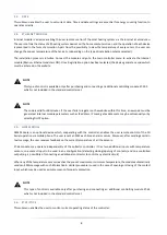
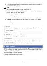
TWO COLLECTORS, PUMP, VALVE, TANK AND ADDITIONAL TANK CONNECTED IN SERIES
Installation 13/17 supports:
➔
collector pump,
➔
switching valve,
➔
solar accumulation tank – with lower circuit,
➔
tank 2 (heated by additional heat source e.g. CH boiler),
➔
one direction of collector positioning,
➔
additional peripherals (no possibility of cooling with DHW
pump)
Installation sensors:
➔
collector sensor,
➔
two sensors of accumulation tank.
➔
tank 2 sensor
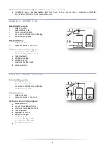
In this system the user may choose the tank which will provide hot water (the controller chooses the tank with higher
temperature). During low insolation periods (winter), the water is taken from the tank 2 (heated by the additional heat
source e.g. CH boiler) whereas solar collector water, heated by the solar heating system, is transported to tank 2 input as
cold water.
Additional parameters to be configured:
•
valve hysteresis

