background image

2

2B

3

4

Bring the power wires to the fixture location in
accordance with local electrical codes.

Connect the white fixture wire to one of the low-
voltage power line wire with the provided outdoor
waterproof wire nut.

Connect the black fixture wire to the remaining low-
voltage power line wire with the provided outdoor
waterproof wire nut.

5

2C

3

5

6

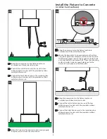
Install the Fixture to Concrete

(or other hard surfaces)

1

2

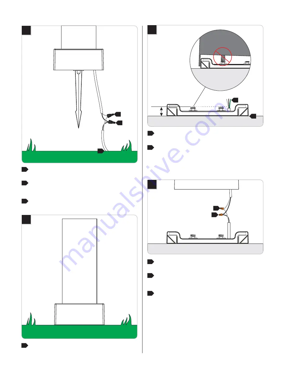
Bring the power wires to the fixture location in
accordance with local electrical codes.

Mount the base plate to an even and smooth surface
using the appropriate template, which can be found on
the following pages. Ensure that length of the lag bolts
or anchor bolts do not exceed 0.58” from the mounting
surface in order to leave enough clearance for the
fixture to fit properly over the base plate.

3A

0.58”

1

2

FIXTURE

BASE PLATE

BASE PLATE

3B

4

5

3

4

Bring the power wires to the fixture location in
accordance with local electrical codes.

Connect the white fixture wire to one of the low-
voltage power line wire with the provided outdoor
waterproof wire nut.

Connect the black fixture wire to the remaining low-
voltage power line wire with the provided outdoor
waterproof wire nut.

5

6

Stake the fixture to the desired location and properly
bury the wire and wire nut connections.

BASE PLATE

Summary of Contents for Zur Pathway 700OAZUR Series

Page 1: ...able installation code by a person familiar with the construction and operation of the product and the hazards involved Use minimum 90 c supply conductors G P I ENERAL RODUCT NFORMATION This product is suitable for wet locations 12VAC input only If using Tech Lighting magnetic transformers this product be dimmed with a low votage magnetic dimmer For all other transformers consult with the manufact...

Page 2: ... using the appropriate template which can be found on the following pages Ensure that length of the lag bolts or anchor bolts do not exceed 0 58 from the mounting surface in order to leave enough clearance for the fixture to fit properly over the base plate 3A 0 58 1 2 FIXTURE BASE PLATE BASE PLATE 3B 4 5 3 4 Bring the power wires to the fixture location in accordance with local electrical codes C...

Page 3: ... place NOTE Maximum rotation of the fixture head is 300º Re install the O rings and socket cap screws reversal of step 1 3 4 4B 5A Use the following instructions along with the provided template to adjust multiple fixtures to the same angle 1 Adjust Multiple Fixture Heads Insert the template in between the head and fixture then align the template edge with the fixture edge Adjust the head to the d...

Page 4: ...4 ...

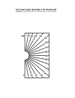
Page 5: ...5 90 80 70 60 50 40 30 20 10 0 100 110 120 130 140 150 160 170 180 FIXTURE HEAD PROTRACTOR TEMPLATE WARNING If printing this template ensure printer settings are set to actual size ...

Page 6: ...6 ...

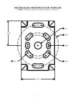
Page 7: ...7 RECTANGULAR MOUNTING PLATE TEMPLATE WARNING If printing this template ensure printer settings are set to actual size ...

Page 8: ...8 Tech Lighting L L C All rights reserved The Tech Lighting graphic is a registered trademark of Tech Lighting L L C Tech Lighting reserves the right to change specifications for product improvements without notification A Generation Brands Company SAVE THESE INSTRUCTIONS ...

Reviews: