background image


          VEGA KS ( 1/2/3) KVA MANUAL 

10 


Figure5Extract UPS front cover 


CAUTION 

A small amount of arcing may occur when connecting the internal batteries. This 
is normal and will not harm personnel. Connect the cables quickly and firmly 

b)


Connect the internal battery connector(see Figure6) 

Connect red to red, Press the connector tightly together to ensure a proper 
connection. 

c)


If you are installing EBPS,see the following section,  “Connectingthe EBP(s),” 
before continuing with the UPS installation. 


Figure6Connecting the UPS Internal Batteries 

Summary of Contents for Vega KS Series

Page 1: ...gent single phase in single phase out high frequency online UPS designed by our R D team who is with years of designing experiences on UPS With excellent electrical performance perfect intelligent monitoring and network functions smart appearance complying with EMC and safety standards The UPS meets the world s advanced level Read this manual carefully before installation This manual provides tech...

Page 2: ...up 5 2 1 Unpack checking 5 2 2 Real panel view 5 2 3 Installing the UPS 7 2 4 UPS start up and turn off 16 2 5 Configuring Battery Setings 17 2 6 LCD control panel 17 2 7 Setup the UPS 18 3 Operations 20 3 1 Button operation 20 3 2 LCD display 21 3 3 UPS setting 27 3 4 Operating Mode Description 30 3 5 Operational Status and Mode s 31 3 6 Alarm or Fault reference code 32 4 Troubleshooting 33 5 Sto...

Page 3: ...s 1 1 Transportation l Please transport the UPS system only in the original package to protect against shock and impact 1 2 Preparation l Condensation may occur if the UPS system is moved directly from cold to warm environment The UPS system must be absolutely dry before being installed Please allow at least two hours for the UPS system to acclimate the environment l Do not install the UPS system ...

Page 4: ...e UPS system is not connected to the building wiring outlet l In order to fully disconnect the UPS system first press the OFF Enter button to disconnect the mains l Prevent no fluids or other foreign objects from inside of the UPS system 1 5 Maintenance service and faults l The UPS system operates with hazardous voltages Repairs may be carried out only by qualified maintenance personnel l Caution ...

Page 5: ...batteries remove wristwatches rings and other metal objects use only tools with insulated grips and handles l When changing batteries install the same number and same type of batteries l Do not attempt to dispose of batteries by burning them This could cause battery explosion l Do not open or destroy batteries Escaping electrolyte can cause injury to the skin and eyes It may be toxic l Please repl...

Page 6: ...se pack the UPS when moving it out from the packaging l Check the appearance to see if the UPS is damaged or not during the transportation do not switch on the UPS if any damage found Please contact the dealer right away l Check the accessories according to the packing list and contact the dealer in case of missing parts It includes 1 UPS user s guide 2 Software Suite CD 3 USB cable 4 Power cord I...

Page 7: ...VEGA KS 1 2 3 KVA MANUAL 6 2KVA S H 3KVA S H ...

Page 8: ...and round mounting holes The rail assemblies adjust to mount in 19 racks with a distance from front to rear around 70 76 cm 27 to 30 inches depth CAUTION l The cabinet is heavy Removing the cabinet from its carton requires a minimum of two people l If installing optional EBP S make sure to install the EBP S directlybelow the UPS so that all wiring between the cabinets is installed behind the front...

Page 9: ...M5 cage nuts and two M5 12 pan head screws to fix the rail assembly to the rear of the rack Figure2Fixing the Rails e Repeat Steps 3 and 4 for the other rail assembly f Tighten the four butterfly nuts in the middle of each rail assembly g If installing optional cabinets repeat Step 1 through Step 6 for each rail kit h Place the UPS on a flat stable surface with the front of the cabinet facing to y...

Page 10: ...on 2 Rackmount Wiring Installation a Installing the UPS including connecting the UPS internal batteries b Connecting any Optional EBP S l To install the UPS NOTEDo not make unauthorized changes to the ups otherwise damage may occur to your equipment and void your warranty NOTE Do not connect the ups power cord to utility until after installation is completed a Remove the front cover of each UPS Pr...

Page 11: ...ill not harm personnel Connect the cables quickly and firmly b Connect the internal battery connector see Figure6 Connect red to red Press the connector tightly together to ensure a proper connection c If you are installing EBPS see the following section Connectingthe EBP s before continuing with the UPS installation Figure6Connecting the UPS Internal Batteries ...

Page 12: ...ourcomputer to one of the communication ports or optional connectivity card For the communication ports usean appropriate cable f If your rack has conductors for grounding or bonding of ungroundedmetal parts connect the ground cable not supplied to the groundbonding screw See Rear Covers for the location ofthe ground bonding screw for each model g If an emergency power off disconnect switch is req...

Page 13: ...e EBP front cover See Figure 10 for the location of thetop EBP cable knockout d If you are installing more than one EBP for each additional EBP remove the EBP cable knockout on the top andbottom of the EBP front cover See Figure 10 for the location of the EBP cableknockouts CAUTION A small amount of arcing may occur when connecting an EBP to the UPS This is normal andwill not harm personnel Insert...

Page 14: ...on g Replace the EBP front cover To replace the cover verify that the EBP cables are routed throughthe EBP cover knockouts cover connects with the cover hook near the left side of theEBP cabinet Repeat for each additional EBP It is the same with the installation of the front cover Refer to install the UPS h Verify that all wires connected between the UPS and EBP s are installedbehind the front cov...

Page 15: ...11 plasticbase installation If anEBP is needed to be placed in the middle the assembly of plastic base is similar Figure 11 The difference is that two 1U plastic base extended boards are added in the middle as the following shows A B C D ...

Page 16: ...cbase installation l The installation between UPS and EBPS can be referred to Fig 13 Figure13The installation for UPS and battery box Figure14 Long backup external battery connection a Install the base then place the RT UPS on the base one by one as Fig 13 shows ...

Page 17: ...er c Once started the UPS will perform a self test function LED will light and go out circularly and orderly When the self test finishes it will come to line mode the corresponding LED lights the UPS is working in line mode 2 Turn on the UPS by DC without mains power a When mains power is disconnected press and hold the ON key for more than half a second to start UPS b The operation of the UPS in ...

Page 18: ...of EBPs installed To ensure maximum battery runtime configure the UPS for the correct number of EBPs refer to Table 8 for the appropriate setting of battery numbers and type Use the up and down scroll keys to select the number of battery stringsaccording to your UPS configuration 2 6 LCD control panel All UPS and EBP Cabinets Number of BatteryStrings UPS only internal batteries 1 default UPS 1EBP ...

Page 19: ... Green On The UPS is operating normally on Oline NOTE When power on or startup these indicators will turn on and off sequentially NOTE On different operation modes these indicators will indicate differently 2 7 Setup the UPS Step 1 UPS input connection Plug the UPS into a two pole three wire grounded receptacle only Avoid using extension cords l For 200 208 220 230 240VAC models The power cord is ...

Page 20: ...lled you can schedule UPS shutdown start up and monitor UPS status through PC The UPS is equipped with intelligent slot perfect for either SNMP or Relay card When installing either SNMP or Relay card in the UPS it will provide advanced communication and monitoring options NOTE USB port and RS 232 port can t work at the same time Step 4 Turn on the UPS Press the ON button on the front panel for two...

Page 21: ... normal mode OFF Button Ø Turn off the UPS Press and hold this button at least 2 seconds to turn off the UPS in battery mode UPS will be in standby mode under power normal or transfer to Bypass mode if the Bypass enable setting by pressing this button Ø Down key Press this button to display next selection in UPS setting mode Ø Exit setting mode Press this button to confirm selection and exit setti...

Page 22: ...rm When the UPS is on battery mode press and hold this button for at least 5 seconds to disable or enable the alarm system But it s not applied to the situations when warnings or errors occur Ø Up key Press this button to display previous selection in UPS setting mode Ø Switch to UPS self test mode Press and hold this button for 2 seconds to enter UPS self testing while in AC mode FUNC OFFButton Ø...

Page 23: ...VEGA KS 1 2 3 KVA MANUAL 22 01 Input voltage 02 Battery voltage 03 Output voltage 04 Load ...

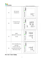
Page 24: ...A MANUAL 23 05 Environment Temperature 06 Firmware Version UPS model 07 CODE Operational status and mode 08 Alarm Code Warming Message All alarm codes are present when abnormal behavior s occur s Part two Tower display ...

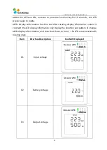
Page 25: ...h rotation function and after rotating display information content is constant the LCD display information only display the direction and pattern of change LCD display after rotation and then shut down to boot the LCD screen saved with rotating state Item InterfaceDescription Content Displayed 01 Input voltage 02 Battery voltage 03 Output voltage ...

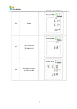
Page 26: ...VEGA KS 1 2 3 KVA MANUAL 25 04 Load 05 Environment Temperature 06 Firmware Version UPS model ...

Page 27: ... 26 07 CODE Operational status and mode 08 Alarm Code Warming Message All alarm codes are present when abnormal behavior s occur s 09 The charging status can also be shown on the screen as below while the charger is on Cc MODE ...

Page 28: ...iscontrolled by 3 buttons FUNC Up OFF Down ON EnterP FUNC Up OFF Down goes into the setting page ON Enter P value adjustment FUNC Up OFF Down for choosing different pages After the UPS turn ON press buttons for 5seconds and then goes into the setting interface page Item Settings Content display 01 Mode setting Press Enter button P to change the setting NOR or ECO or CF Press UP button to select th...

Page 29: ... button to select the next setting 03 Frequency setting Press Enter button P to change the setting 50 or 60Hz Press UP button to select the previous setting Press DOWN button to select the next setting 04 Battery capacity setting Press Enter button P to change the setting Battery capacity range is 1 200Ah Press UP button to select the previous setting Press DOWN button to select the next setting ...

Page 30: ...N button to select the next setting 06 Bypass voltage lower limit setting Press Enter button P to change the setting The bypass voltage lower limit range is 170 220Vac Press UP button to select the previous setting Press DOWN button to select the next setting 07 Mute setting Press Enter buttonP to change thesetting ON or OFF Press UP button to select the previous setting Press DOWN button to save ...

Page 31: ...S will work in line mode charge the battery and protect the load Battery Mode The battery yellow LED ison and the buzzer beeps once per 4 seconds When the mains power down or instable UPS will turn to Battery Mode at once If the mains recovers the UPS will transfer to line mode If battery voltage low alarm activates the indicator of battery LED flashes If battery voltage reaches low limit UPS will...

Page 32: ...n ECO Mode If the utility in out of ECO range but still in Line range the UPS will transfer to Line Mode Utility tolerance ofECO Mode can be set Fault Mode When the UPS has fault The warning red LED is on and the buzzer beeps The UPS will turn to fault mode If you turn on the UPS without the Fan and the LCD display fault codes At the moment you can press the OFF key to shut down the UPS when the m...

Page 33: ...ED lit 9 Fan fault Beep continuously Fault LED lit 12 Selftest fault Beep continuously Fault LED lit 13 Battery Charger fault Beep continuously Fault LED lit 15 DC Bus over voltage Beep continuously Fault LED lit 16 DC Bus below voltage Beep continuously Fault LED lit 17 DC bus unbalance Beep continuously Fault LED lit 18 Soft start failed Beep continuously Fault LED lit 19 UPS Inside Over Tempera...

Page 34: ... seconds Battery LED lit 41 Bypass Not Available BPS LED blinking 42 Bypass unable to trace BPS LED blinking 43 Inverter on invalid 44 Not at Inverter side 4 Troubleshooting If the UPS system does not operate correctly please solve the problem by using the table below and theTrouble Shooting Chart Symptom Possible cause Remedy No indication and alarm even though the mains is normal The AC input po...

Page 35: ...use short circuit occurs on the UPS output Check output wiring and if connected devices are in short circuit status Alarm code is shown as 9 and FAULT led light Fan fault Contact your dealer Alarm code is shown as 01 02 15 16 17 18 A UPS internal fault has occurred Contact your dealer Battery backup time is shorter than nominal value Batteries are not fully charged Charge the batteries for at leas...

Page 36: ...s C heck LC D i nf orm at i on C heck U PS out put vol t age B U S vol t age End C heck sps 12V B at vol t age R epl ace pow er board R epl ace cont rol panel N o N o Fan i ssue LC D i ssue R epl ace f an R epl ace cont rol panel Yes Yes N o R epl ace cont rol panel U PS Faul t no out put R f er t o al arm Faul t code ref erence N o R epl ace pow er board N o Yes R epl ace cont rol panel N o R epl...

Page 37: ...e please contact your dealer l Storage Before storing charge the UPS 5 hours Store the UPS covered and upright in a cool dry location During storage recharge the battery in accordance with the following table Storage Temperature Recharge Frequency Charging Duration 25 C 40 C Every 3 months 1 2 hours 40 C 45 C Every 2 months 1 2 hours Be sure to deliver the spent battery to a recycling facility or ...

Page 38: ... range 40 70Hz Power factor 0 99 100 load Nominal Input Voltage Bypass voltage range Bypass high voltage point 230 264 setting the high voltage point in LCD from 230Vac to 264Vac Default 264Vac Bypass low voltage point 170 220 setting the low voltage point in LCD from 170Vac to 220Vac Default 170Vac Generator input Support OUTPUT Output voltage 200 208 220 230 240Vac Power factor 0 9 Voltage regul...

Page 39: ...ormal 110 130 UPS transfer to bypass after 5 seconds when the utility is normal 130 UPS transfer to bypass immediately when the utility is normal Short Circuit Hold Whole System Overheat Line Mode Switch to Bypass Backup Mode Shut down UPS immediately Low battery voltage Alarm and Switch off EPO optional Shut down UPS immediately Audible Visual alarms Line Failure Battery Low Overload System Fault...

Reviews: