background image

ST-65  module GSM v1.0.7

VI. CONTACT AND TEMPERATURE SENSORS

Module ST-65 has 2 additional sensor connectors, one contact and one 
controlled   output,   operating   independently   from   the   boiler   controller, 
with a universal application:

1) Two   connectors   intended   for   connection   of   temperature   sensors 

(KTY) marked as 

T1, T2

 (option – no sensors in the set). The scope 

of sensors settings is within the range from - 10 to + 85

o

C.

2) One connector detecting short circuit/opening of contacts. Marked as 

Wej

  (option – no cable in the set). The connector enables a very 

broad scope of applications (e.g. as an anti-burglar sensor, included 
in the set with a limiting switch).

3) One controlled Output. Marked as 

Wyj

 (e.g. a possibility to connect 

additional contactor to control any electric circuit. See: page 14). 

To   activate   the   operation   of   the   chosen   connector,   select   and 

highlight,   in   the   submenu,   the   item   "

active". 

For   joints   of   type   T 

(sensors), additionally set the maximum and the minimum temperature, 
the occurrence of which will be signalled by an sms message. For the 
connector contact (Wej type) select the type of event (short circuit or 
opening) the occurrence of which will be signalled by an sms message.
From that moment, the module will inform:

  For   connectors   of   type   T,   on   measured   temperatures   i.e.   the 

current, the minimum, the maximum, measured in a given cycle* and 
also on errors of sensors.

  For   connectors   of   Wej   type,   in   the   case   of   occurrence   of   the 

selected   event,   that   is   detecting   a   short-circuit   or   opening   of   the 
contact.

cycle

 – is a period between subsequent sms messages.

8

 -

Summary of Contents for ST-65

Page 1: ...tech 1...

Page 2: ...g Directives of the European Union RTTE 1999 5 EC LVD 2006 95 EC EMC 2004 108 EC Harmonized norms applied to assess compliance with the basic requirements of the aforementioned EC Directives PN ETSI E...

Page 3: ...observe the prohibitions concerning mounting the module in areas labelled with a ban on using devices emitting radio waves II APPLICATION The GSM module is a device cooperating with the controllers of...

Page 4: ...4 PLUS fitting ANTENNA GSM EXIT CANCELLING THE SETTINGS PLUG FOR COMMUNICATION WITH THE CONTROLLER ST 65 MENU VIEW MINUS fitting ENTERING THE MENU CONFIRMING THE SETTINGS POWER SUPPLY 9V DC INPUT CONT...

Page 5: ...itch to standby mode waiting for the card to be changed wait for a message as above To insert the card unscrew four fixing screws and open the casing 5 MENU CHANGING THE SIM CARD NOTIFICATION GSM SETT...

Page 6: ...Sim card pin Note The sim card pin is not masked in the module menu in the event of using the card for a different purpose pin code should be changed to a new one NOTE Replacement of the sim card in...

Page 7: ...No name Value Temp CO 23 current temperature Hot tap water 25 current temperature 1 Set CH 60 set temperature 2 Set HUW 40 set temperature The quantity and the type of sent data depend on settings an...

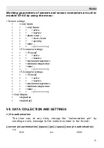
Page 8: ...as Wyj e g a possibility to connect additional contactor to control any electric circuit See page 14 To activate the operation of the chosen connector select and highlight in the submenu the item acti...

Page 9: ...nactive maximum temperature minimum temperature name T2 connector settings T2 on off active inactive maximum temperature minimum temperature name Conf Outputs default on default off VII DATA COLLECTIO...

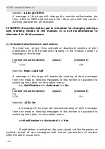
Page 10: ...message in the format current pin authorization space command e g 1234 Off Namely from 1234 Off A message of this type will deactivate sending of alert messages from the module Sending messages in th...

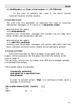
Page 11: ...ption with the controller incoming sms information messages will contain data both from the boiler controller and from active contact and temperature sensors 4 Output activation Each GSM controller by...

Page 12: ...tion e g 9999 W 1 30 Namely 9999 W1 30 Message of this type will activate outputs W for 30 minutes In order to deactivate output W send a message in the format pin authorization W value e g 9999 W 0 N...

Page 13: ...ng parameters Sending a message of this type is equivalent to a change in the menu of module ST 65 GSM settings Phone number 1 or 2 Where by means of up down buttons we select the telephone number of...

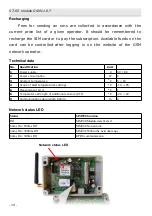
Page 14: ...rator Technical data No Specification Unit 1 Power supply V 9V DC 2 Power consumption W 2 3 Ambient temperature O C 5 50 4 Scope of alert temperatures settings O C 10 85 6 Measurement error O C 1 8 9...

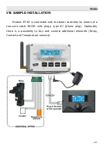
Page 15: ...odule ST 65 is connected with the boiler controller by means of a four core cable RS232 with plugs type RJ phone plug Optionally there is a possibility to buy and connect additional elements Relay Con...

Page 16: ...ries and accumulators used in EU member countries and in other European countries having their own collection systems Never throw a battery into the fire Waste batteries should be obligatorily sent fo...

Page 17: ...to develop and improve the product please send any comments concerning program errors or abnormal controller operation states directly to the address SERWIS TECH serwis techsterowniki pl phone no 48...

Page 18: ...ST 65 module GSM v1 0 7 18...

Page 19: ...ACT AND TEMPERATURE SENSORS 8 VII DATA COLLECTION AND SETTINGS 9 1 Pin authorization 9 2 Activation deactivation of alert notices 10 3 Operation mode 11 4 Output activation 11 5 Change and activation...

Page 20: ...tech 20...

Reviews: