background image

ST-77 – Manual Guide

TECH

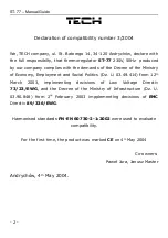
Declaration of compatibility number 3/2004

We, TECH company, ul. St. Batorego 14, 34-120 Andrychów, declare with 

the full responsibilty, that thermoregulator 

ST-77

 230V, 50Hz  produced 

by our company complies with the demands of the Decree of the Ministry 

of Economy, Employment and Social Politics (Dz. U. 03.49.414) from 12

th 

March   2003,   implementing   decisions   of   Low   Voltage   Directiv 

73/23/EWG

, and the Decree of the Ministry of Infrastructure (Dz. U. 

03.90.848)   from   2

nd

  February   2003   impplementing   decisions   of  

EMC 

Directiv 

89/336/EWG

.

Harmonised standards 

PN-EN 60730-2-1:2002

 were used to evaluate 

compatibility.

For the first time, the product was marked 

CE

 on 4

th

 May 2004

Co-owners:

Paweł Jura, Janusz Master

Andrychów, 4

th

 May 2004. 

- 2 -

Summary of Contents for ST-77

Page 1: ...ST 77 Manual Guide...

Page 2: ...of Economy Employment and Social Politics Dz U 03 49 414 from 12th March 2003 implementing decisions of Low Voltage Directiv 73 23 EWG and the Decree of the Ministry of Infrastructure Dz U 03 90 848 f...

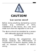
Page 3: ...he device etc one must make sure that the regulator is not live The device should be intstalled by a person with adequate electrical training and certificates Before starting the programmer one should...

Page 4: ...mperature the regulator is in a cycle of work in which the fan works all the time fuel feeder working time is set up by the user both the time of work and the time of break have to be set up if the th...

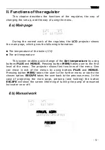
Page 5: ...buttons PLUS and MINUS Pressing button MENU takes user to the first level of the menu The projector shows first two lines of the menu One can move in ech of the menus by using buttons PLUS and MINUS...

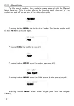
Page 6: ...other elements Pressing button MENU starts the fuel feeder The feeder works until button MENU is pressed again Pressing MENU turns the fan on off Pressing button MENU turns the water pump on off Pres...

Page 7: ...n the boiler Wrong set up of both the feeder working time as well as the feeder break time may cause faults in the work of the boiler i e coal may not get burnt in full or the boiler may not reach the...

Page 8: ...resis of the set temperature in the boiler It is a difference between the set temperature so the temperature the user wants to have in the boiler and the temperature that is in the boiler at a certain...

Page 9: ...t these are the fan s gears The higher the gear the faster the fan works Gear 1 is fan s minimum speed and gear 6 is fan s maximum speed Changes between gears can be introduced by pressing buttons PLU...

Page 10: ...ported until it reaches the the set temperature If the set temperature is reached CHW pump is turned off and the CH pump is turned on CH pump continues working until the temperature in the boiler drop...

Page 11: ...se in the time set by the user alarm is activated the feeder and the fan are automatically turned off water pump is turned on off independenty and the sound signalling is turned on The screen projects...

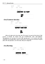
Page 12: ...rature of turning CH and CHW pumps on It is turned off after reaching the temperature set on the boiler CHW pump is turned on again after the temperature on the boiler drops 10 degrees II n Burning 12...

Page 13: ...e fuel and the boiler Caution Wrong set up of the described functions may cause constant increase in the temperature The time of break of burning shouldn t be too short II o Producer s settings The re...

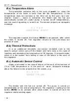
Page 14: ...tections It is an additional bimetallic mini sensor installed next to the boiler s sensor which cuts off the feeder and fan s exits in the case of reaching and exceeding the temperature of 90 degrees...

Page 15: ...C the regulator will turn the feeder and the fan on and it will work until reaching the set on the boiler temperature III e Temperature Safety Protections The regulator is equipped in an additional pr...

Page 16: ...he effectiveness of the engines earthing pump CHW pump fan and feeder L p Specification Units 1 Current Supply V 230V 50Hz 10 2 Power Consumption W 4 3 Ambinet Temperature O C 0 40 4 Load of the Circu...

Page 17: ...and surge tank that protect the boiler from boiling of water in the central heating system must be installed VI a Diagram of the regulator s cabling installation Additional attention has to be paid d...

Page 18: ...regulator 10 II k Alarm 11 II l Function of the constant CH pump 11 II m Summer function 12 II n Burning 12 II o Producer s settings 13 III Safety Protection 13 III a Temperature Alarm 14 III b Therma...

Page 19: ...arantee does not include faults that occurred due to the wrong use of the product or those that are the user s fault mechanical faults or those that appeared after atmospherical discharge overvoltage...

Page 20: ...Notes...
Reviews: